|

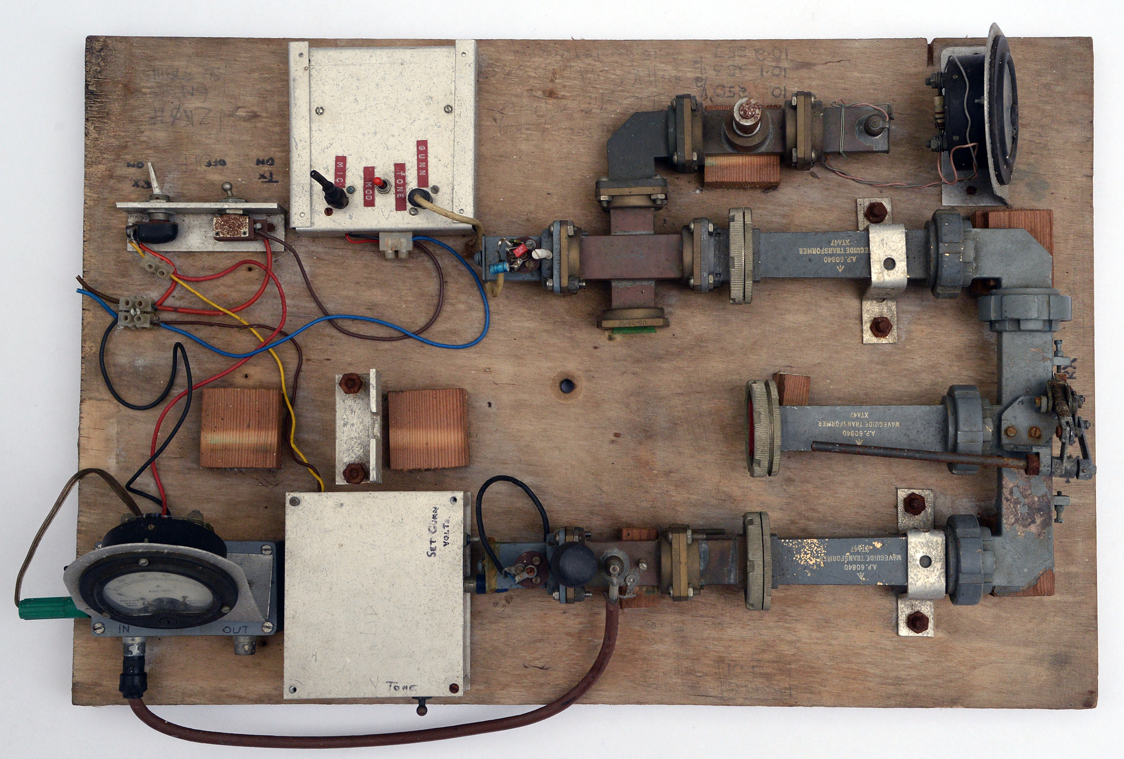
The complete breadboard. For a picture of it in use see G2DSP's QSL card.
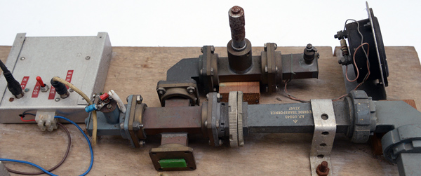
G4ETU's 10 GHz wide-band transceiver features a waveguide switch and separate Rx and TX sections. The wooden base board measures 600 x 390 mm.
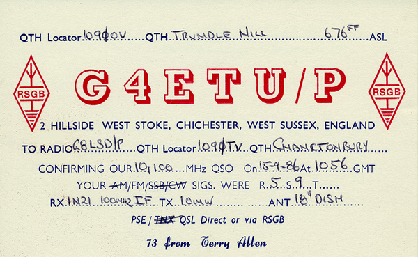
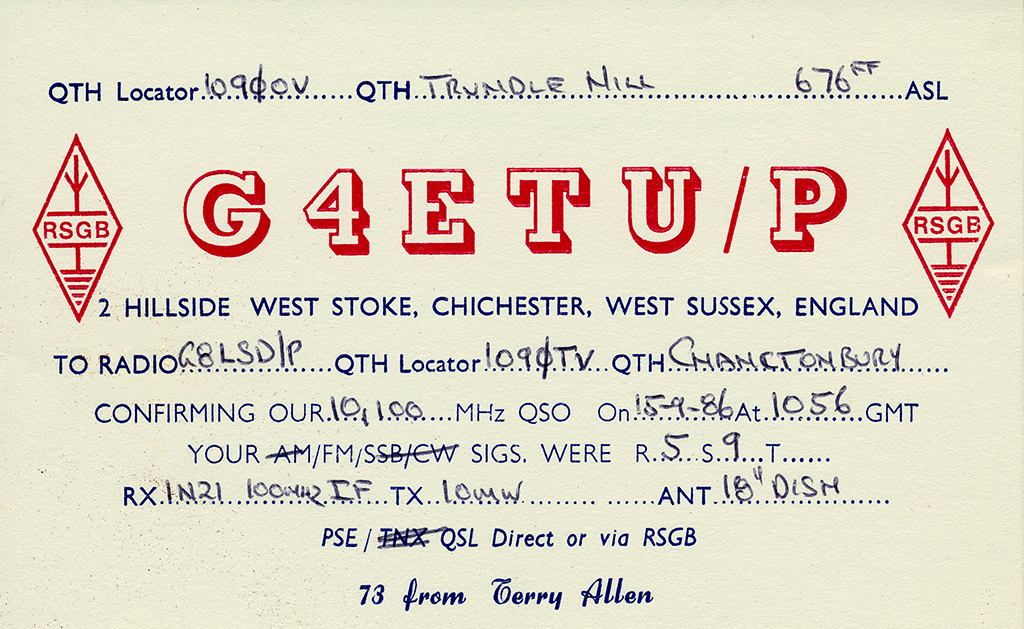
The QSL card gives details of the TX and RX as was normal.
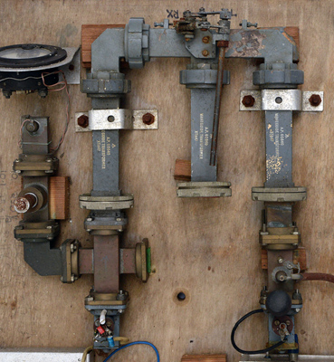
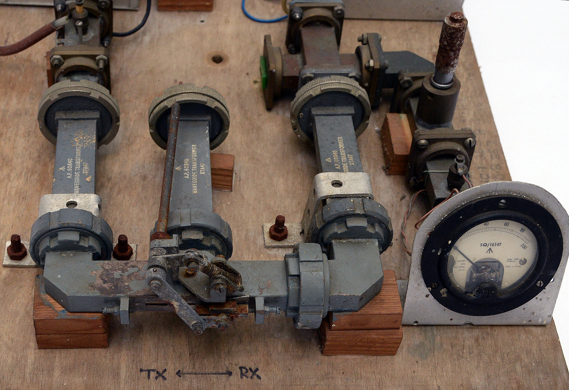
The waveguide components.
The switch features waveguide transformers as the main switch body is not WG16. The switch operates by rotating the control rod. Sadly the switch is corroded and very difficult to move.
The transmit line is on the left with micrometer adjusted wavemeter. The identical Gunn oscillators are at the bottom of the image. The receiver PTFE tuning screw is fitted with an adjustment knob.

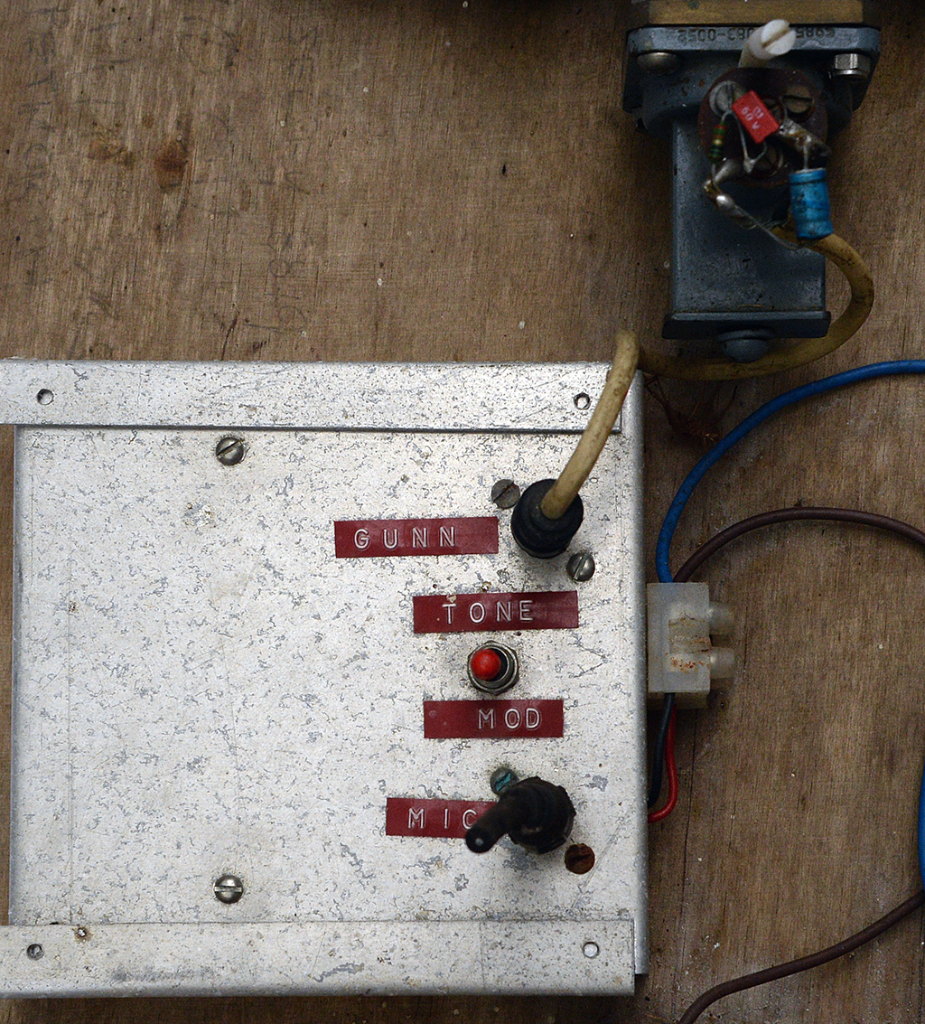
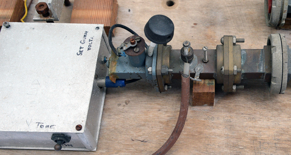
The transmitter Gunn supply.
The transmitter Gunn supply and Gunn oscillator in a small section of WG16. The power supply offers a choice of speech or tone modulation.

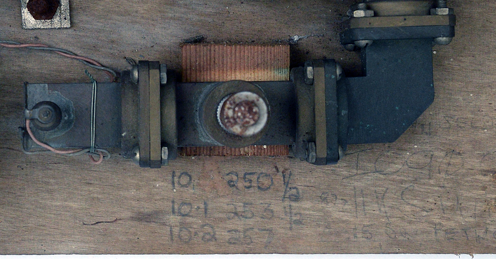
Waveguide switch.
The receive line is on the left and transmitter on the right. The writing on the breadboard refers to the direction of rotation of the switch shaft. The mechanism moves within a slot in the waveguide.
Receiver.
The aluminium box houses the Gunn supply and a tone generator. There were times where searching for a carrier with the receiver tone switched on made it easier to locate a weak signal. The LO signal passes through to the mixer diode and the resultant IF signal at 100 MHz is passed to the pre-amp.
Transmitter.
The RF from the Gunn source passes through a directional coupler and then on to the waveguide switch. The directional coupler samples a portion of the RF and passes it to the wavemeter. After the wavemeter cavity is a detector diode connected to a meter. In use the meter will show a dip in reading when the signal resonates with the wavemeter cavity.

On the board is marked the frequency and corresponding micrometer setting. With the micrometer cavity set, the PTFE screw on the Gunn source was adjusted until the meter dip was observed.
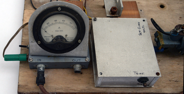
Receiver mixer current meter.
With separate TX and RX sections the receiver Gunn oscillator was run to give the optimum mixer current. In this was the mixer was arranged to be at its most sensitive. A noise figure of around 16 dB was typical. The IF pre-amplifier is contained in the box under the meter.
|