|
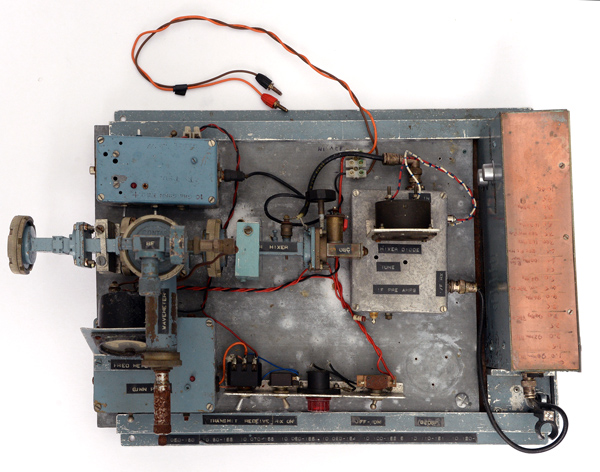
The complete 10 GHZ tranceiver with connection in WG16 to dish. The board is 460 x 340 mm.
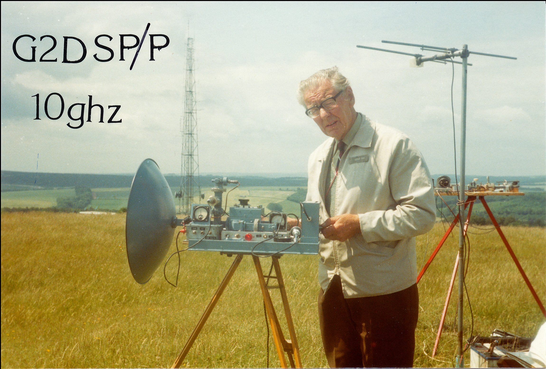
Wide-band portable operation from a hill top lent itself to a design that had controls on all sides as the equipment would be tripod mounted. This bread-board style is typified by the equipment built by the late Ron Allen G2DSP, one of the early pioneers of microwave operation in the south of England. It is a wide-band FM system with both voice and tone modulation. His later 24GHz wide-band system was constructed in a similar way.
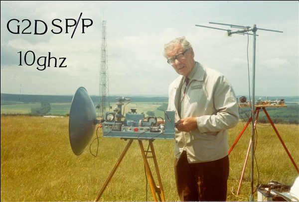
Ron at the Trundle with this equipment. The full sized version of this image shows that the original build used a separate TX oscillator with a waveguide switch. In the background is the 10 GHz equipment of G4ETU.
Ron was very well known and one of the 'main players' in the southern UK microwave scene. This equipment was in regular use in the mid 1980's and was probably made in the late 1970's.
Ron lived at Bognor Regis and had permission to operate from the Trundle Hill Goodwood. To access his site he obtained the gate key and then pushed his gear to the top of the hill in a barrow. His dish was 24 inches diameter and he mounted the gear on a stout wooden tripod.
Ron was a keen constructor and made not only his own gear but the equipment used by some others including his cousin Terry G4ETU. The late Ern Downer G8GKV had equipment built in the same bread-board style.

Two Gunn power supplies can be seen on the left of the image.
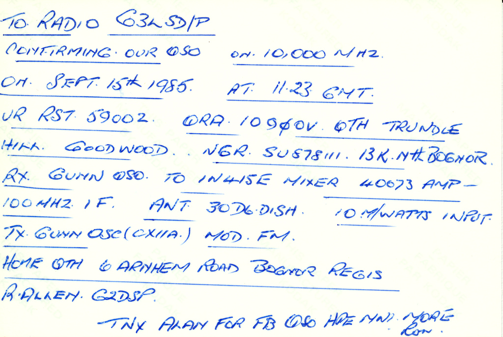
This tranceiver has been modified as there are two Gunn power supplies, RX and TX, but only one is actually used. The image on his QSL card shows the original version of the transceiver.
The tranceiver uses a Gunn source with the RF passing through an in-line mixer. After the mixer there is a directional coupler to a wavemeter for frequency measurement. On transmit the mixer diode current is an indication of the RF and a meter is connected to measure this. On receive the Gunn oscillator is set above or below the signal to produce an IF output. Common practice at the time in the South was to use a tuneable IF at around 100 MHz and that is the case here. The signal from the mixer passes through a pre-amp and then on to the IF system. The tuneable IF is in reality a Band II FM broadcast receiver. The Gunn device oscillates optimally at a set voltage and so the power supply is a stabilised variable voltage. The Gunn frequency is also variable over a small range by altering the drive voltage. This gives rise to the Gunn power supply being voltage modulated. The microphone input is amplifier for this purpose but for establishing a contact the receiving station has a greater chance of finding the signal if it is modulated rather than just producing a weak thump as the receiver is tuned across the carrier. To this end the Gunn power supply can be modulated by a tone. This is normally a simple 1 kHz square wave based on the 555 timer or similar.
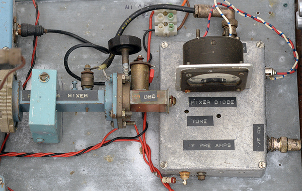
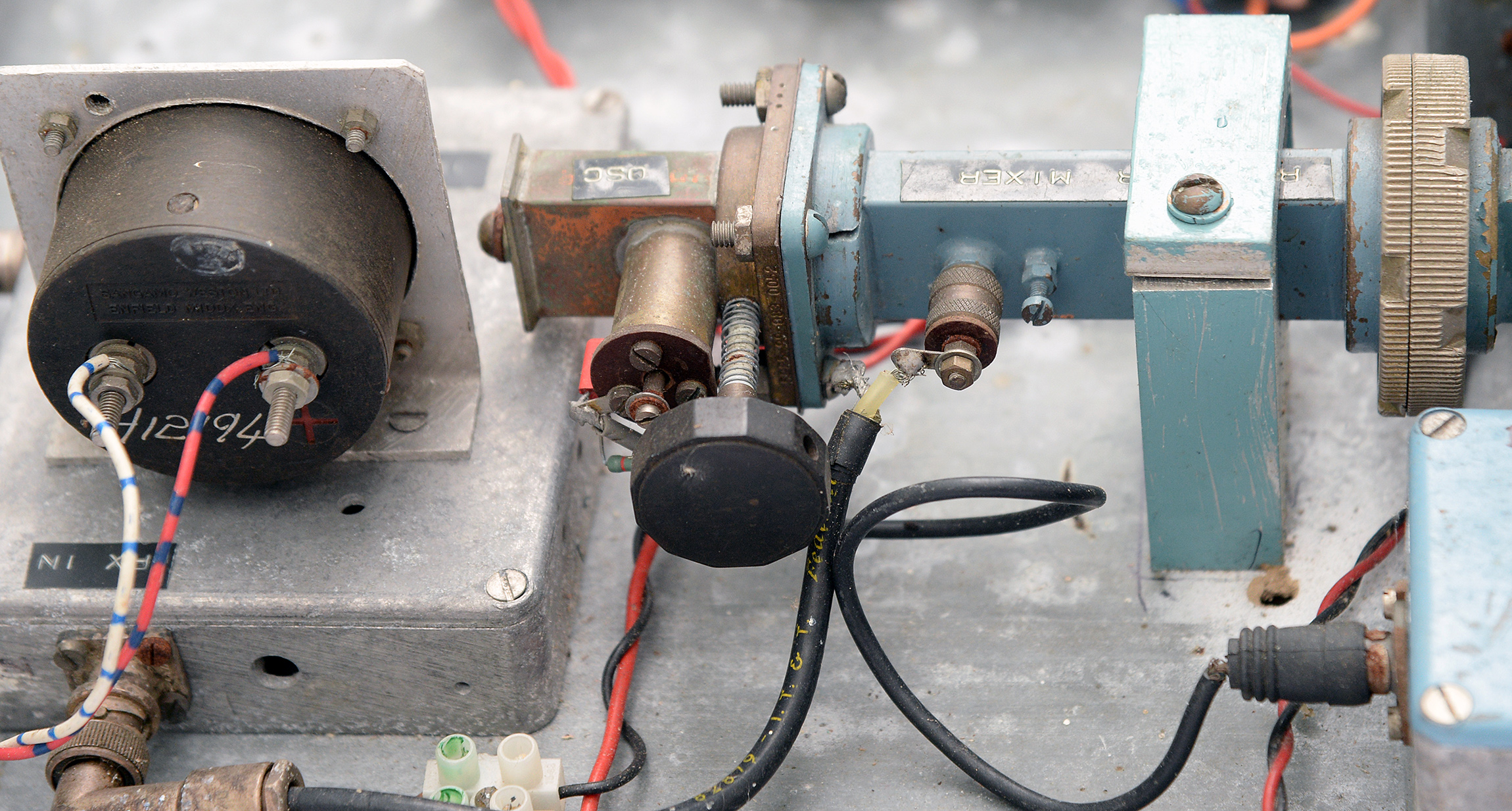
The main RF components.
The Gunn source is home made and produced before commercial sources became available on the surplus market. The adjacent mixer also looks to have been home made. Ron was an accomplished constructor and at the end of the wide-band era he built the 10 GHZ JVL mixer and achieved a few hundred micro Watts of RF from it. He made some successful contacts from his home QTH using this narrow-band system.
The mixer connects to the IF pre-amp and mixer current monitor. With a dual oscillator system the RX oscillator drive was adjusted to give the optimum mixer current. The in-line systems tended to have the mixer diode offset in the waveguide so as to provide a compromise between RX diode matching and TX power output.

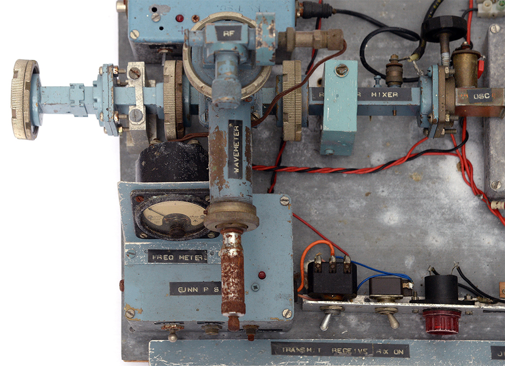
The rear of the main 10 GHz components.

A closer view of the tuning screw. Note the mixer matching screw and the screw in the oscillator end wall that defines the cavity.
Set into the flange at the output end of the Gunn source is a PTFE threaded rod. The tip of the rod penetrates the waveguide and this alters the frequency of oscillation. The threaded rod has a spring around it to minimise backlash.
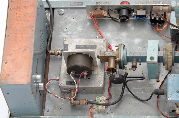
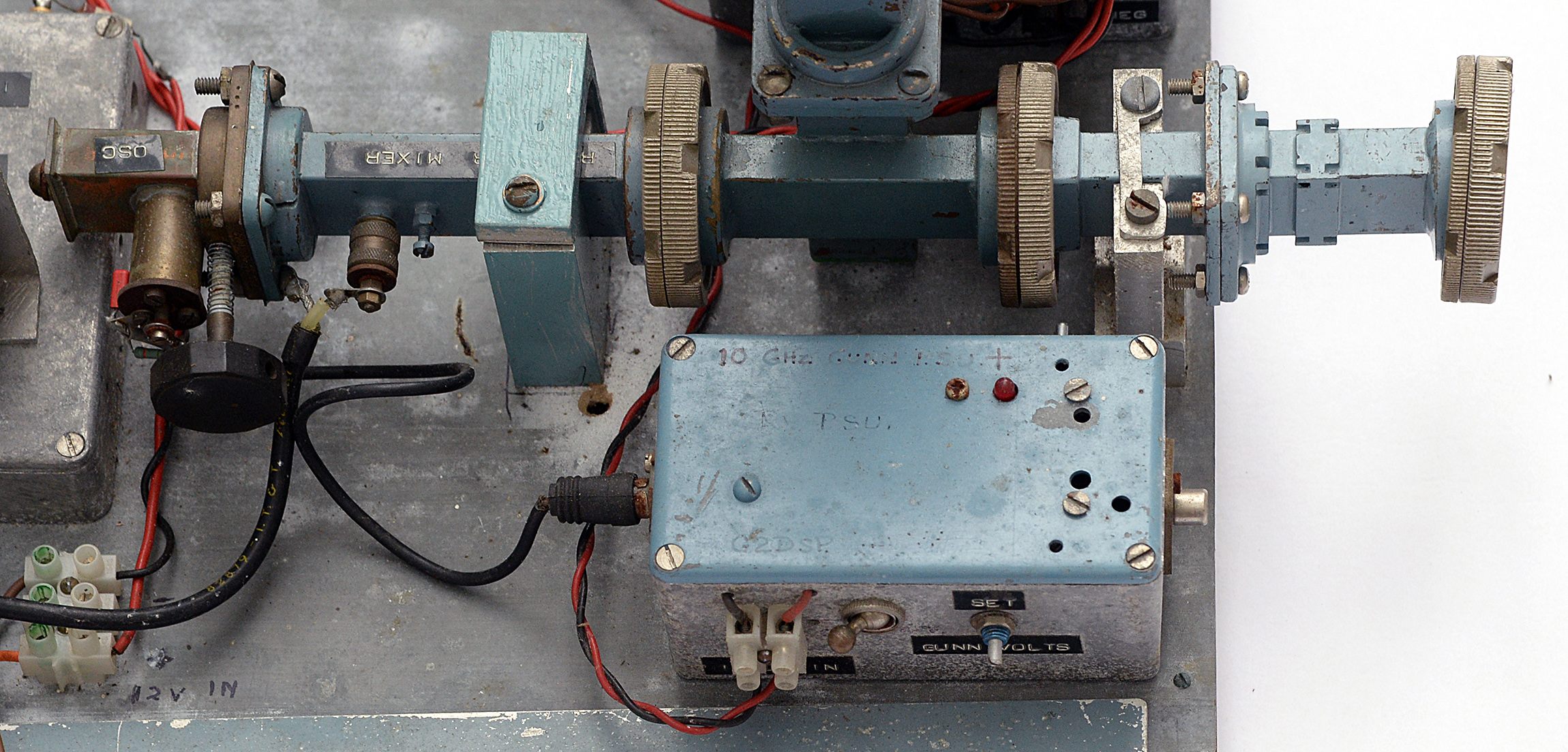
The 100 MHz IF is on the left.
The Gunn power supply and modulator is on the right. External controls allow for the Gunn voltage to be set. The mixer output is taken in co-ax to the pre-amp box. The mixer current monitor can be seen connected to the pre-amp box. The pre-amp output connects to the tuneable IF and it generates the final audio. Like broadcast FM 10 GHz wide-band systems used 75 kHz FM modulation. Contrast this to the later narrow-band systems operating in 2.4 kHz bandwidth.
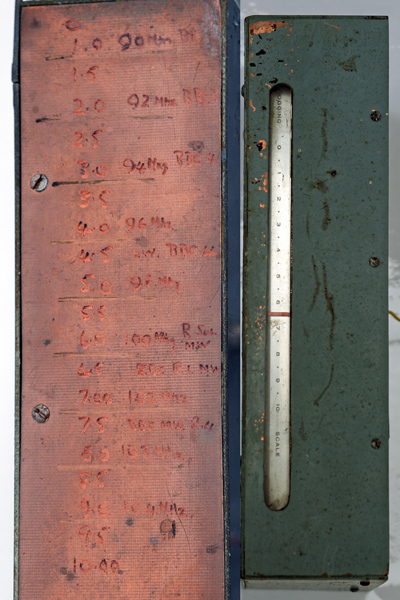
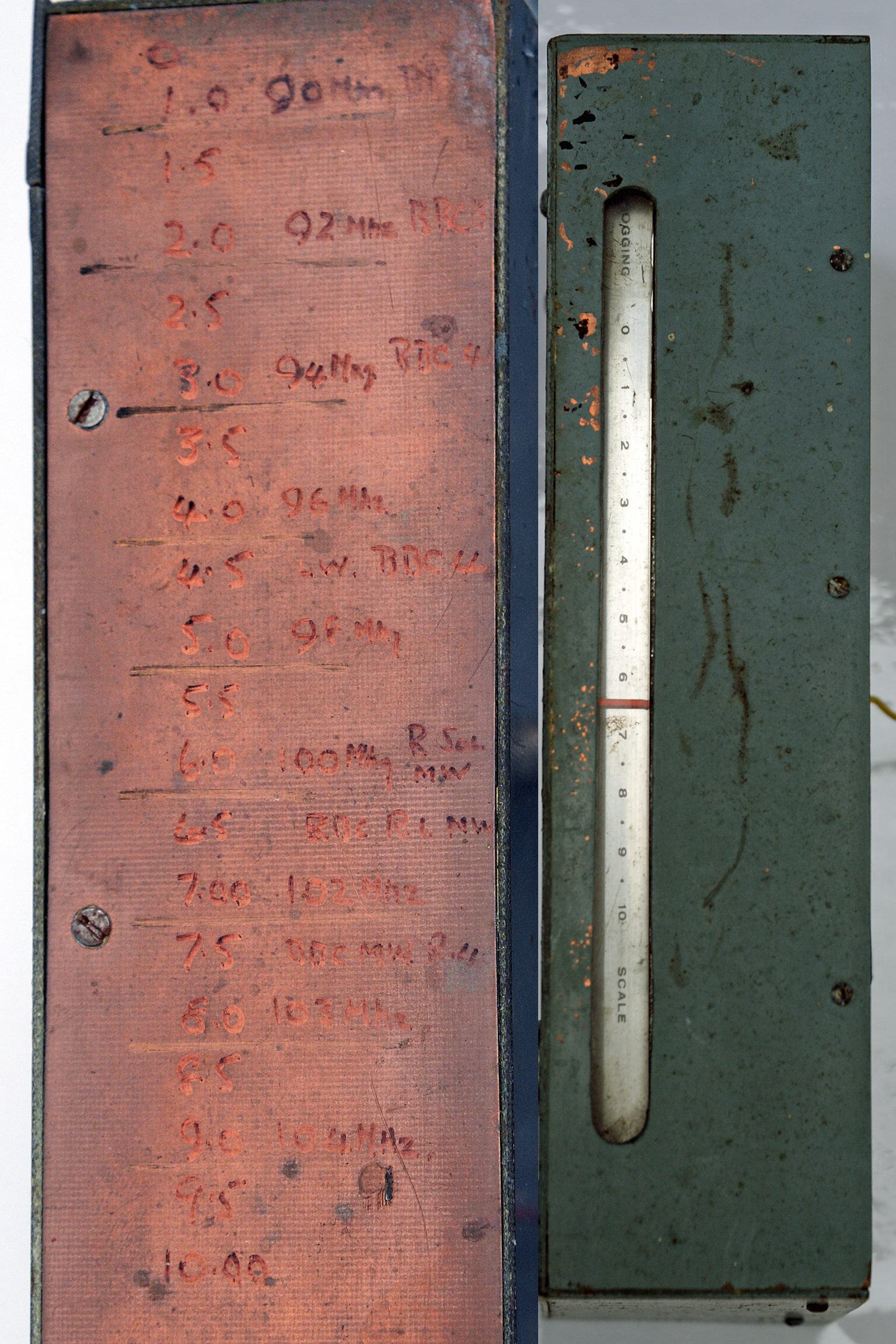
Tuneable IF calibration.
Even in the mid 1980's the Band II broadcast band was empty enough for this to be a viable way of providing a tuneable IF for a 10 GHz wide-band system. The calibration written on the top of the case includes the position of the BBC stations. At around 100 MHz the band was usually clear enough for this frequency to be used without breakthrough.
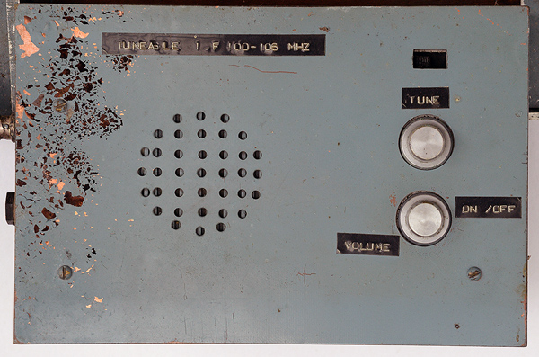
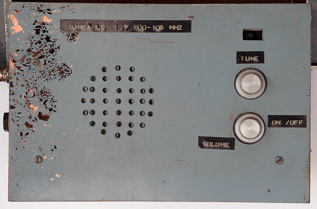
The face of the FM IF box.
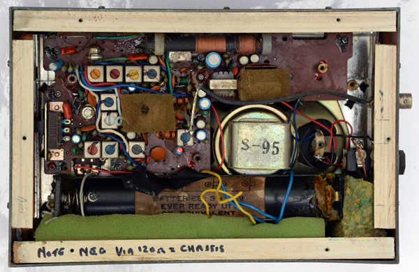
The broadcast receiver inside the IF box.
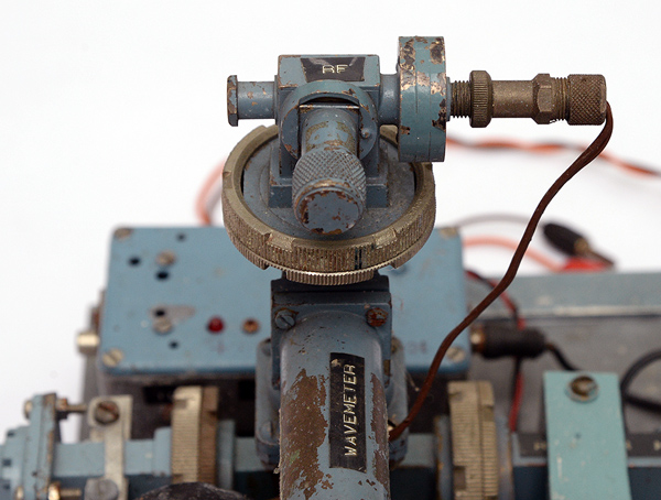
The wavemeter.
The wavemeter connects to the directional coupler and is a cavity tuned by a micrometer controlled plunger. When the cavity resonates with the signal, the meter connected to a mixer diode on the far end of the wavemeter will show a dip in reading. I know that Ron had an accurate Wayne Kerr wavemeter and this could have been used to calibrate the wavemeter seen here.
The wavemeter has two uses: on transmit the wavemeter micrometer would be set to the desired frequency and the Gunn source tuned until the wavemeter meter reading dipped, on receive with a known IF frequency the micrometer can be adjusted to determine the frequency of the input signal.
Back in 1985 I (G8LSD) tested my PW EXE in a local transmission to Ron. The test lasted but a few moments as Ron was able to show that I was transmitting low, in fact outside the band. A re-adjustment then set my lowest frequency to 10,000.00 MHz.

QSL card reverse with equipment specs.
|