|
Introduction
Since the design of the G3JVL 10 GHz narrow-band transverter was published, much interest has been shown in this device. A large number have now been built (including four by the author) and much experience has been gained in both their construction and alignment. What follows is an attempt to expand somewhat the original description in the light of this experience.
Construction
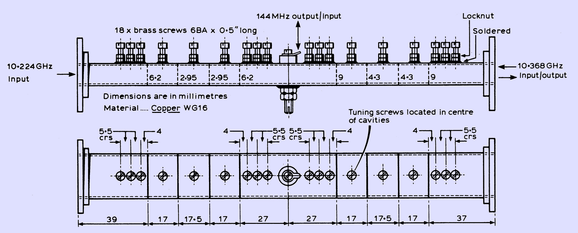
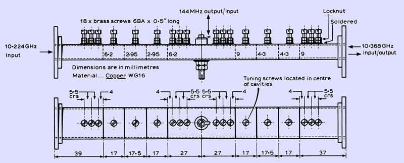
Two modifications to the design can simplify the tuning-up procedure considerably. These are the construction of the mixer and step-recovery diode multiplier as two separate units, and a minor modification to the arrangement of the matching screws. These modifications are shown in the main illustration above. With this arrangement it has been found convenient to use the G8DEK multiplier, exactly as described in Microwaves (March 1976). The overall length of the multiplier, from the front of the flange to the rear short-circuit, was 29 mm in the author's versions. An attractive feature of this design is the built-in attenuator pad in the input circuit, which results in very stable operation due to the high degree of suppression of interactions between the multiplier and the output stage of the 378.666 MHz exciter. The price for this, of course, is an increased drive requirement (1.5-2.5 W) of the multiplier, but this is more than outweighed by the improved stability. A point not made in the original description of the multiplier is that the diode should be mounted with its heatsink end (ie that end remote from the flange) in the 2 BA screw.
The original mixer design also called for the use of copper screws for cavity tuning to minimize losses. In practice it has been found that the use of brass screws instead of copper ones causes hardly any degradation in noise figure, and so it would seem not worth the extra trouble involved in manufacturing copper screws.
The construction of the mixer can be made as easy as possible if a careful procedure is followed. There are several 'irreversible' stages, which must be done in the correct order to avoid later trouble. First saw off a length of waveguide and roughly square off its ends by filing. Mark out the positions of the iris slots carefully (aim for plus or minus 0.1 mm accuracy). The slots may then be cut out using a junior hacksaw (with a new blade!), starting at each corner and working inwards towards the centre to maintain the accuracy of each cut. All holes are then marked out and drilled 2.3 mm (6 BA tapping). The centre hole must be drilled carefully, using a vertical drill, through both walls of the waveguide. The upper hole is then opened out to 3/32 in and the bottom to 4 mm (2 BA tapping). This hole is then tapped 2 BA, and the 18 holes for the tuning and matching screws tapped 6 BA.
Next, the whole assembly is carefully deburred by running a file through the waveguide. This tends to push metal back into the holes and slots, which are then cleared using the hacksaw and appropriate drills and taps. Further filing and cleaning out should be repeated until all traces of burrs and loose metal are removed. The final deburring operation is to run a 4 mm drill through the 2 BA tapped hole just into the 3/32 in hole, and rotate slowly by hand to cut a slight chamfer on the inside wall of the waveguide. This ensures a flat surface for the diode post to be mounted against, with no burrs remaining to puncture the insulation.
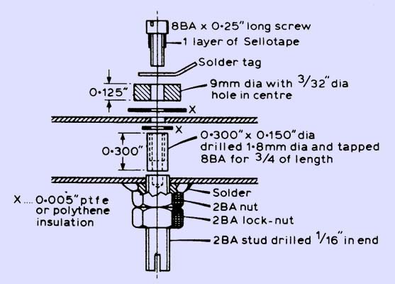
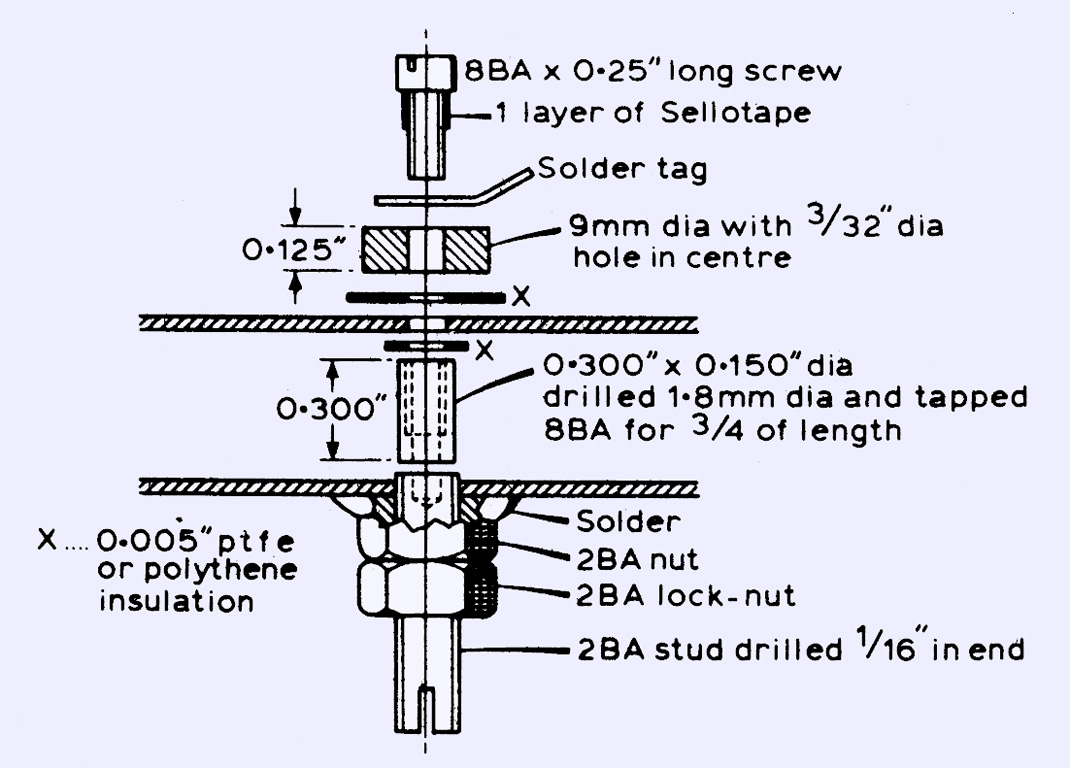
The arrangement of the mixer diode mount.
Details of the mixer diode mount are shown above. After manufacturing the component pieces of this, deburr the surfaces which are to be mounted against the walls of the waveguide, by rubbing them on emery paper placed on a flat surface. The diode mount should then be assembled and checked for insulation, and for alignment using a scrap diode. For this operation the 2 BA nut should be screwed up against the waveguide wall by hand. Should the diode not quite fit, the upper hole may be filed slightly so that the assembly may be moved to the correct position. A very useful tool for checking the alignment of diode mounts of this type can consist of a 2 BA screw with a 1.8 mm diameter pin turned on one end. This is used in place of the 2 BA screw and scrap diode referred to above, and will positively assure that the mount is correctly aligned. The importance of this cannot be too highly stressed, as a mount which is out of alignment will result in broken diodes (an expensive experience!). When the diode mount has been checked, it should be dismantled. In order tO obviate problems later on, ensure that the 0.3 by 0.150 in piece will pass freely through the 2 BA nut and the 2 BA tapped hole in the waveguide. If not, open these out slightly with a suitable drill.
The next items to be made are the iris plates. These are manufactured form 0.9 by O.5 in pieces of 0.024in copper sheet which have been carefully filed to size; the 0.5 in dimension, not being as critical as the 0.9 in dimension, which should be in the range 0.895 - 0.900 in. The iris holes are drilled centrally in the plates; the diameters of these are given in the top picture. After deburring and flattening the plates between two smooth pieces of metal in a vice, they may be assembled into the waveguide. The 6 BA nuts which are to be soldered to the waveguide are jigged in place using cadmium-plated or stainless steel screws. Old steel or brass screws which are sufficiently corroded not to take solder easily can also be used.
The assembly is then soldered, using a hotplate to provide the heat-direct heating with a flame is much less satisfactory. A suitable hotplate could consist of a piece of 1/8 in aluminium plate on a domestic cooker ring. Perhaps the most critical part of the construction of the mixer is this soldering stage, as too much solder or flux inside the cavities can introduce excessive losses and/or detuning. Thus the cleaning of all parts to a bright finish before soldering is necessary. If all the parts are clean it should only require the application of a small amount of solder to each side of the irises to solder them. However, be careful that no gaps remain after soldering. The author has found 18 swg Multicore solder to be ideal for this operation. Speed is essential. or the copper oxidises and becomes more difficult to solder. In this context the temperature of the hotplate should be only just high enough so that the solder runs freely.
When all the 6 BA nuts and upper sides of the irises have been soldered, the waveguide is turned on its side and the bottom iris joints soldered, applying the solder to the tops of the joints. The 2 BA nut is then jigged in position (using a suitable screw) as described above. and soldered. Next, the flanges are fitted in position, having been pre-heated on the hotplate. and soldered. A small amount of waveguide should be left sticking out of the flanges, to be removed later by rubbing on a sheet of emery paper laid on a flat surface. which then leaves a well-finished surface. Remove the assembly from the heat and, when it has cooled to just below solder melting point, solder several solder tags to the top and bottom walls of the waveguide using an iron. These are to act as anchoring points for the IF preamplifier housing.
When the unit has fully cooled, remove all the jigging screws and run a 2 BA plug tap through the nut and into the waveguide. The tap should be inserted vertically upwards and withdrawn vertically downwards to reduce the chance of metal dust falling into the cavity. This tapping operation ensures that the 2 BA diode-mounting screw runs freely in the thread. Next, the diode mount may be re-assembled. This must be done in the following way to avoid losing pieces inside the waveguide, which are then very difficult to retrieve (as the author knows to his cost-twice!).
Pass a 1 in-long 8 BA screw through the top hole and out through the 2 BA nut. Place the small insulating washer over the screw, and screw on the 0.3 by 0.15 in post hand-tight. Then pull this piece through the 2 BA nut up against the inside wall of the waveguide, and insert a 2 BA screw or, preferably, the alignment tool mentioned above, and screw in until the post is pushed firmly against the wall. The 2 BA screw is then removed and the top part of the diode mount assembled. The 2 BA screw is removed and replaced by the 2 BA diode-mounting screw complete with diode. In order to avoid dropping the diode inside the cavity, the screw and diode are held with the diode uppermost and then fitted vertically upwards into the waveguide. The screw is tightened by hand so that the diode is held in place, and the locknut tightened up. Diode removal is achieved by slackening off the locknut, unscrewing the 2 BA screw one turn, tapping the screw gently sideways to release the diode from the upper post, and then unscrewing downwards. The mount itself can.be dismantled, if required, by reversing the assembly sequence.
Initial tuning-up
As with the construction, the alignment of the unit is much simplified by the adoption of a logical procedure. The first step is to connect a multimeter to the diode, via short leads to reduce the risk of transient pickup, which could damage the diode.
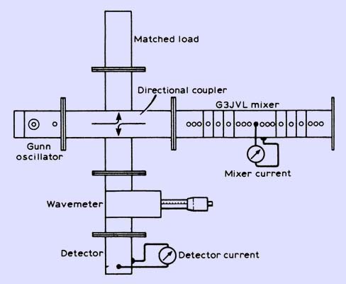
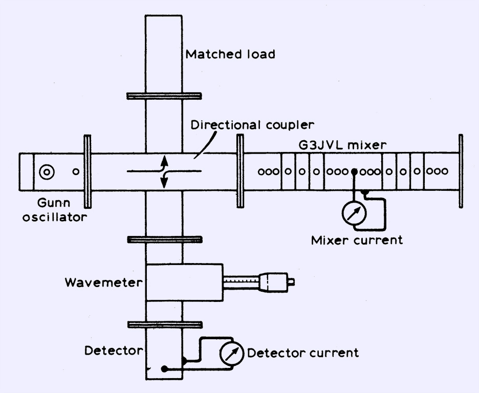
Waveguide test set-up for aligning the mixer.
Next, the waveguide test bench shown above should be assembled from the station 10 GHz (wideband) equipment. The directional coupler is oriented so that the detector current is a monitor of reflected power, ie the current should be very small or zero with a matched load connected in place of the mixer, and several hundred micro-Amps with the mixer in place (and off tune). Set the Gunn oscillator to 10,368 MHz and connect the signal input end of the mixer to the directional coupler. The procedure is to then adjust the first filter tuning screw (ie that tuning screw nearest to the directional coupler) until a sharp change is seen in the level of reflected power, indicating resonance. The three matching screws in front of the filter should not be inserted at this stage. Leave the tuning screw at the position of resonance, and adjust the second cavity tuning screw for a similar effect. Adjust the third tuning screw likewise, and then repeat the adjustment of the three screws until no reflected power is indicated. Recheck constantly during the alignment that the Gunn oscillator is still on frequency, as it is possible that its frequency may be affected by the tuning of the cavities.
At this point there should be an indication of a few micro-Amps on the meter connected to the mixer diode (referred to below as the 'mixer current'), indicating some transmission of power through the filter. If no current is indicated, slowly insert a matching screw into the hole nearest to the signal filter, on the mixer diode side of the cavity. As the reflected power is seen to rise, readjust the tuning screw in the adjacent filter cavity for minimum reflected power. As this procedure is continued with increasing penetration of the matching screw, at some point some mixer current should be seen. When some mixer current has been obtained, readjust the filter tuning screws, and insert matching screws on either side of the signal filter and experiment with their penetration until maximum mixer current is obtained. As all the screws tend to interact with each other to some extent, it is necessary to go several times round the 'loop' until the optimum settings are found. A mixer current of several milli-Amps should be achieved using a 5-10 mW Gunn oscillator.
Lock the screws in position, re-adjusting if necessary to maintain the tuning, remove the mixer from the directional coupler and re-connect the other way round. Reset the Gunn oscillator to 10,224 MHz and repeat the above procedure for the local oscillator section of the mixer. Do not interfere with the tuning and matching screws associated with the signal filter. Since the local oscillator filter is somewhat narrower in bandwidth than the signal filter, it is rather more difficult to adjust, and greater care will be necessary.
The step recovery multiplier should be aligned next. Connect its output to a detector and, on application of drive at 378.666 MHz to the multiplier, some current should be seen in the detector. Maximize this by repeated adjustment of the tuning screw, the two trimmer capacitors and the variable resistor on the multiplier. When several milli-Amps of detector current have been obtained, the multiplier may be transferred to the mixer unit, whereupon some mixer current should be observed. This is maximized by repeated adjustments of the multiplier and the local oscillator filter and its associated matching screws. The mixer current should then be at least 1.0 mA, and possibly as high as 5 mA. The final tuning-up stages require the use of the IF pre-amplifier, and will be discussed later. Before proceeding further it is best to remove the mixer diode to avoid any chance of damage by transients during subsequent soldering operations.
A Suitable IF Preamplifier
No information was given in the article concerning IF pre-amplifiers. Since the noise figure of a mixer is partly dependent on the noise figure of the subsequent receiver, a low-noise IF pre-amplifier is vital. For optimum performance this should be mounted on the waveguide assembly.
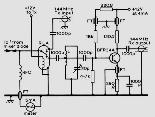
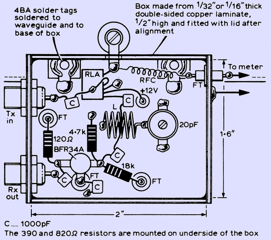
Circuit diagram of a suitable IF pre-amplifier and changeover system. All 1,000 pF capacitors are miniature ceramic plate types. L: 5t 18 SWG 0.55 in long 0.25 in internal diameter, tapped at 2.5t. RFC: 20t, 26 SWG, closewound 0.15 ID. RLA: RS type 349 591 or equivalent. FT: 1,000 pF feedthrough capacitors.
The circuit and suggested layout of a suitable pre-amplifier are shown above and below. Note that if receive-only operation is required the relay may be omitted.
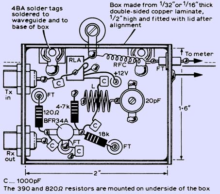
Layout of the IF pre-amplifier.
Final Alignment
The final alignment of the mixer requires the use of an automatic receiver alignment aid, such as that referred to in Microwaves (October 1979). First adjust the 20 pF trimmer in the preamplifier for maximum receiver noise. Then connect up the alignment aid and reset the trimmer for best noise figure. Adjustments may then be made to all the tuning and matching screws for best noise figure, although these are somewhat interactive, and it may take time to reach the optimum settings. Once an optimum has been found the output power on transmit can be checked by applying sufficient drive (5-20 mW) at 144 MHz to approximately double the mixer current. This drive may be obtained from the station 144 MHz transceiver via a suitable attenuator with an adequate power rating. The settings for maximum transmit power and best noise figure do not coincide exactly, and it will be necessary to compromise if real transceive operation is intended. However, if it is expected to use the unit mainly as a receiver, then optimize for best noise figure only.
Additional Information
The original Microwaves item on the G3JVL mixer specified a BXY41E diode for the multiplier and an AEI DCI304 GaAs Schottky diode for the mixer. The former device is no longer readily available, while the latter is somewhat expensive. Some cheaper, more readily available diodes manufactured by Microwave Associates have recently been tested, with very satisfactory results indeed. A suitable replacement for the BXY41E is the MA44150, while the MA40150 and MA4E024 devices have performed very well as mixers, both with noise figures of 7.5 dB. This is not quite as good a performance as that measured by the author using the DC1304C device, which had a 6.5dB noise figure, but is still very acceptable. These noise figures refer to the overall system using the IF preamplifier described above feeding a 3 dB noise figure 144 MHz receiver.
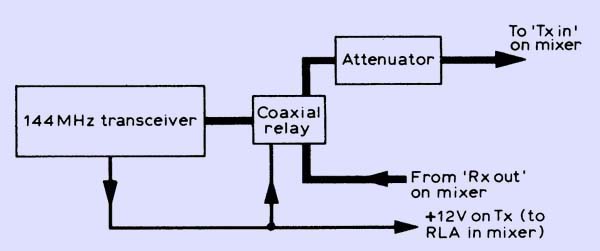
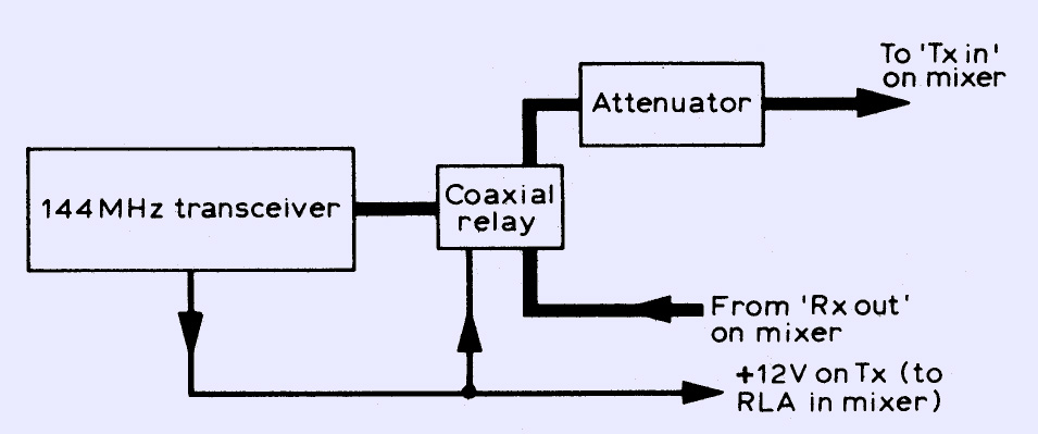
Block diagram of a complete 10 GHz transceiver.
If full transceive operation is intended it will be necessary to add a coaxial relay, switched by the 144 MHz transceiver PTT line to switch the transceiver from the receiver output socket to the transmitter il)put socket, as shown above. The value of attenuation required in the transmit line should be such as not to overdrive the mixer. Suitable starting values are 2O dB for a 3W output 144 MHz exciter and 25 dB for a 10W exciter. Extra attenuation should be inserted until the 10 GHz output just starts to decrease; the attenuator can then be rebuilt to that value. It is important to ensure that the resistors comprising the attenuator will handle the power safety, since any failures could result in a large drop in attenuation with the consequent risk of damage to the mixer diode.
Little has been said concerning the 378.666MHz exciter. This is of course a crucial part of the system, and careful attention must be paid to its design in several respects. The most important of these concerns the noise generated by the crystal oscillator. A noisy oscillator can seriously degrade the overall noise figure; this problem beset early experimenters on 10 GHz narrow-band. Also, the oscillator must be extremely stable, implying the use of high quality crystals as well as a good circuit. An exciter designed specifically for use with this mixer is the High Quality UHF Source for Microwaves currently being developed.
In use, few problems have been found with this design. One thing which it specifically dislikes is water finding its way into the cavities, so operation in wet weather requires careful attention to be paid to waterproofing the unit. Most constructors mount the mixer, together with the changeover system and 378.666MHz exciter, in a large die-cast box. Also, some de-tuning of the cavities can occur over extremes of temperature, usually resulting in low mixer current. The first screw to adjust in this event is the local oscillator filter tuning screw nearest to the mixer. Do not attempt to move two screws at once, or the mixer may well go permanently out of alignment. Some more cautious operators have been known to take automatic noise figure optimization equipment out with them in the field, but this is not usually necessary.
Finally it should be recognized that this design is most definitely not for the beginner on 10GHz, both in respect of its relative complexity and the absolute necessity for test equipment, albeit homemade, for tuning it up.
|