|
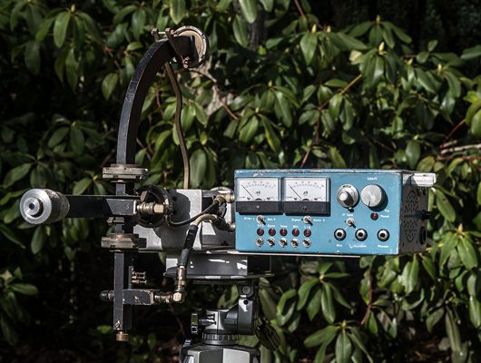
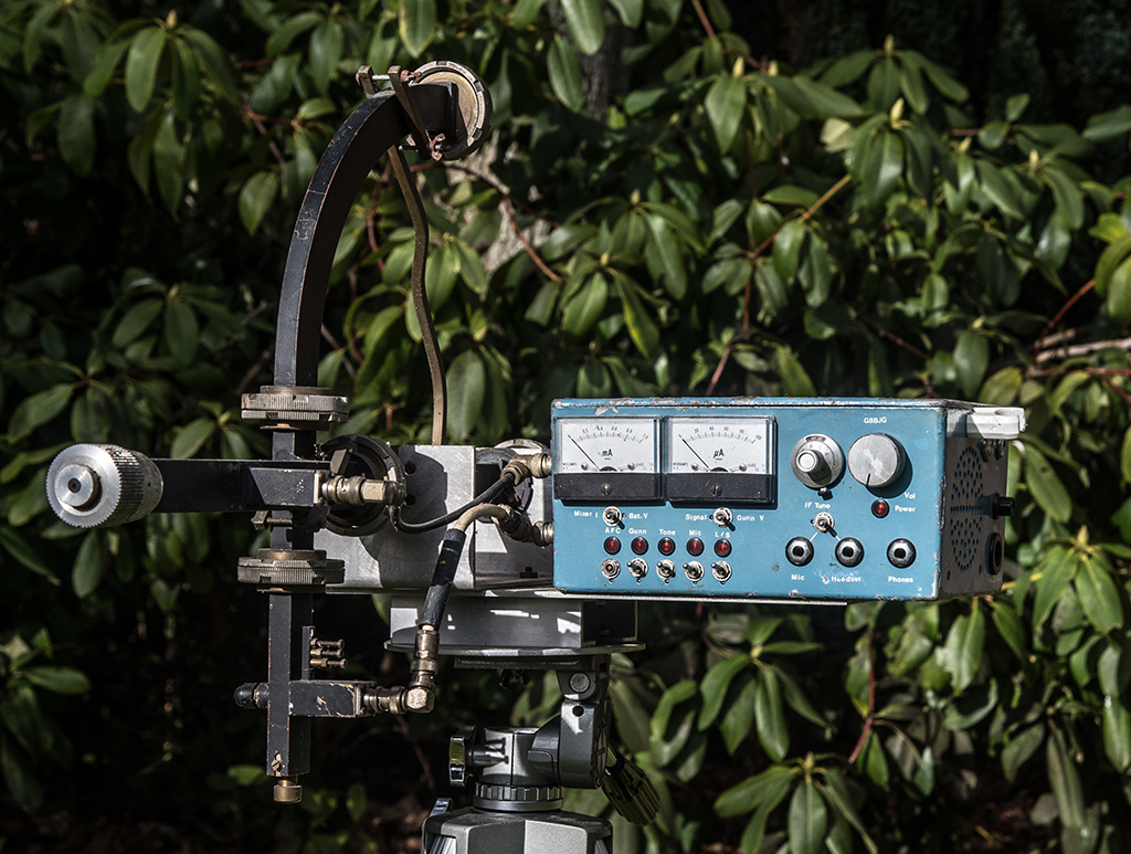
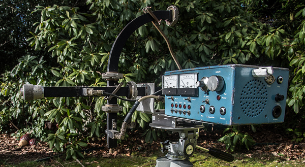
Alan chose to use a waveguide Gunn oscillator and mixer rather than the Pascal head used by G8LSD et al. The diecast box is the size specified in the articles 222 x 144 x 103mm.
The PW EXE was published from June 1981. Full construction details were presented in the PW articles. These provided a starting point to newcomers to 10 GHz and a useful guide to existing microwavers.
The 1980s were a time of the north south divide. We, in the south, all worked around 10.1 to 10.2 GHz and further north the groups used 10.4 GHz. The equipment was set for one or the other.
The move to narrow-band operation using crystal controlled equipment gathered momentum in 1988 and soon wideband operation all but ceased.
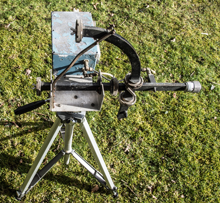
Like most of us Alan kept his wideband gear and donated this equipment to the museum in 2016. For this write-up the equipment was mounted on a tripod and as an experiment it was powered-up. It immediately came to life and received an FM broadcast. My 10.1GHz wideband beacon was switched on and received with only a small alteration of the tuning micrometer. The waveguide caps remained in place. Apart from the peeling paint the only defect is a broken AFC switch.
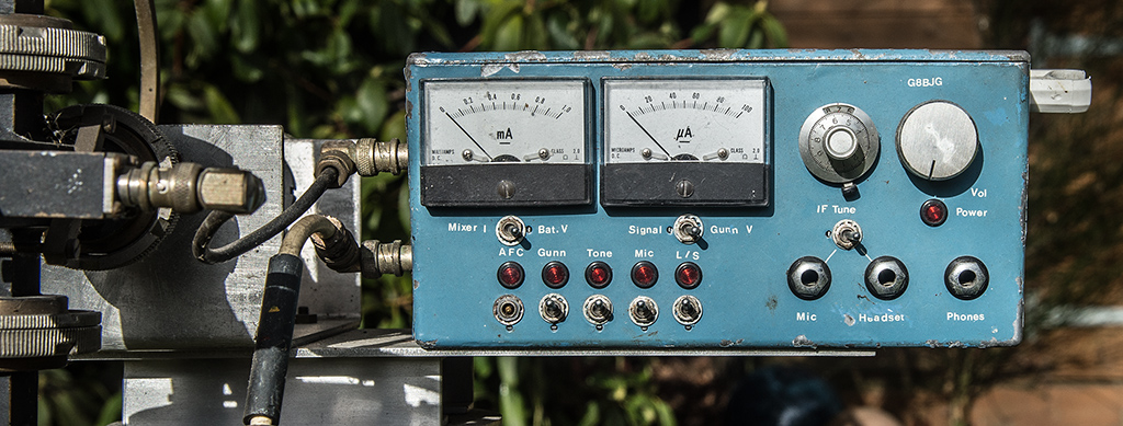
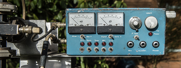
Unlike the basic PW EXE this transceiver features an audio VOGAD based on the then popular Plessey SL6270C chip to increase the 'talk power' and a preamplifier operating at the first IF frequency of 100 MHz.
The waveguide is designed to use separate horns or dishes for TX and RX.
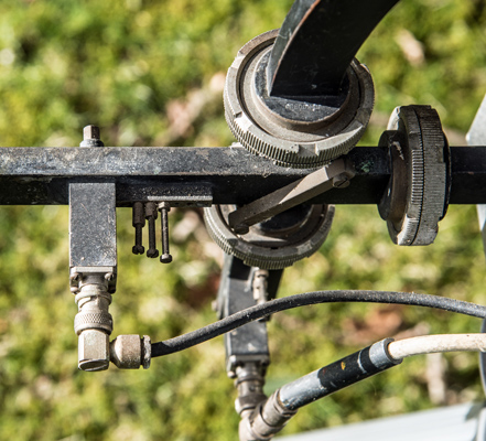
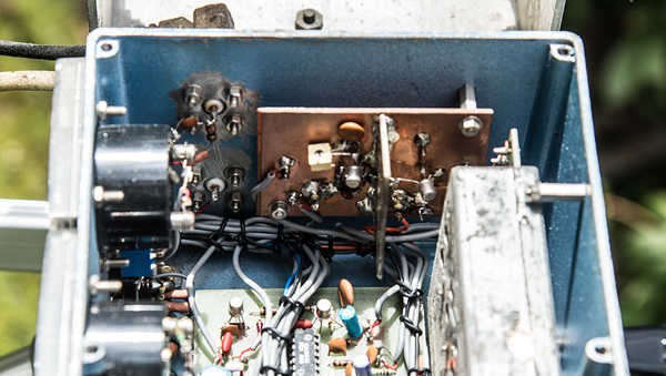
The Gunn oscillator is on the horizontal waveguide and a directional coupler feeds a part of the RF into the mixer arm (vertical).
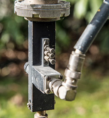
The mixer: the diode is within and the three screws provide matching.
On the left is the oscillator tuning. A micrometer head alters the internal length of the waveguide cavity.
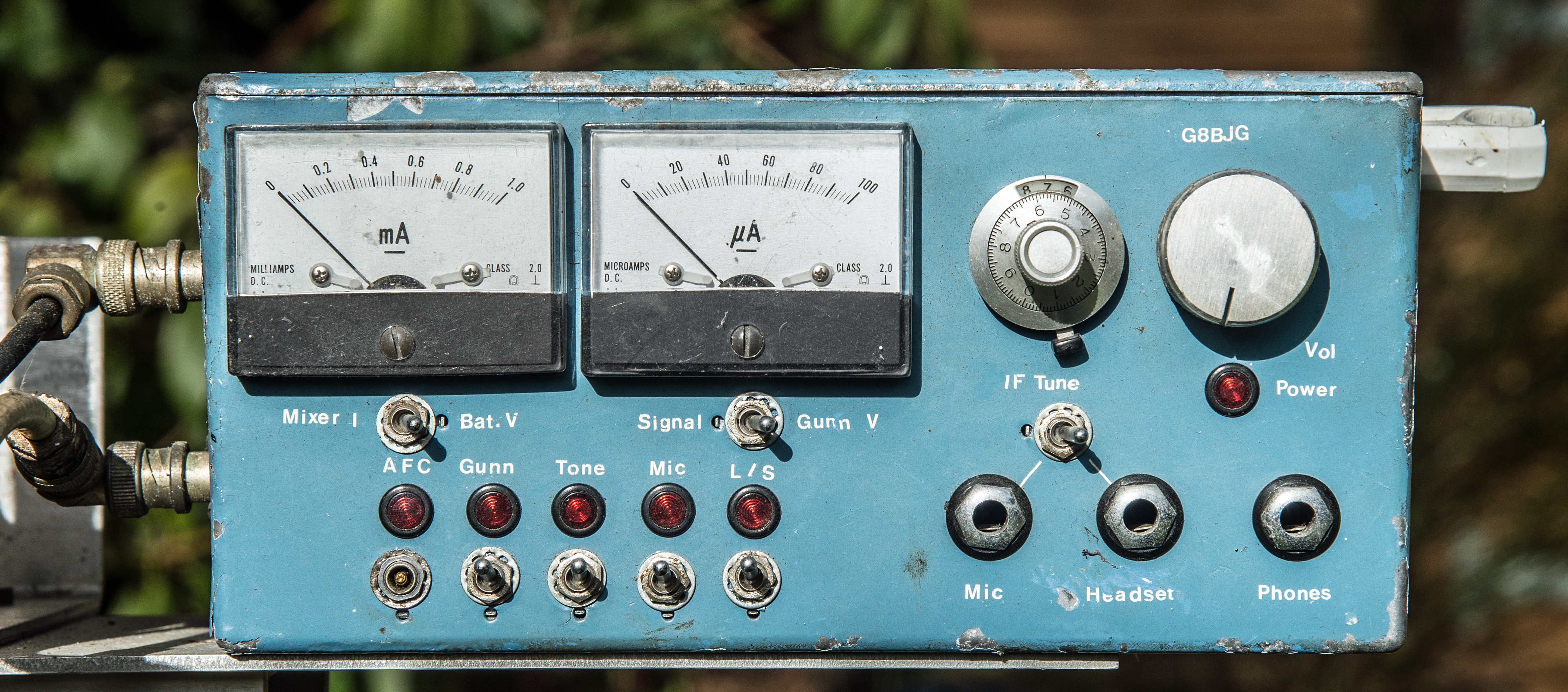
The excellent engineering of the transceiver.

Click this image for a supersized image.

A closer view of the front panel.

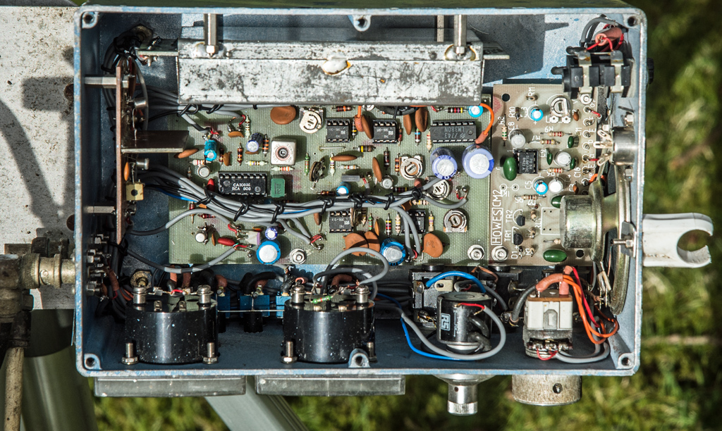
The internal layout. RF pre-amp vertical on the left, the VOGAD board on the right. The VHF Tuner head is mounted vertically (top) and the main circuit board is flat on the base of the box.
Click for a supersize image. Note the professional wiring.

The speaker end with VOGAD board as microphone pre-amplifier.
The 100 MHz pre amplifier on a PCB ground plane and central screen.
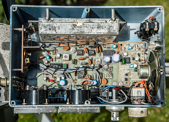
The Band II tuner head is varicap tuned and the tuning voltage is set by the multiturn pot with locking dial on the outside. The one with RS on the side.
|