|

This 10.1 GHz personal beacon was designed and built in the mid 1980s to provide a reference signal when operating portable with the PW EXE 10 GHz system.
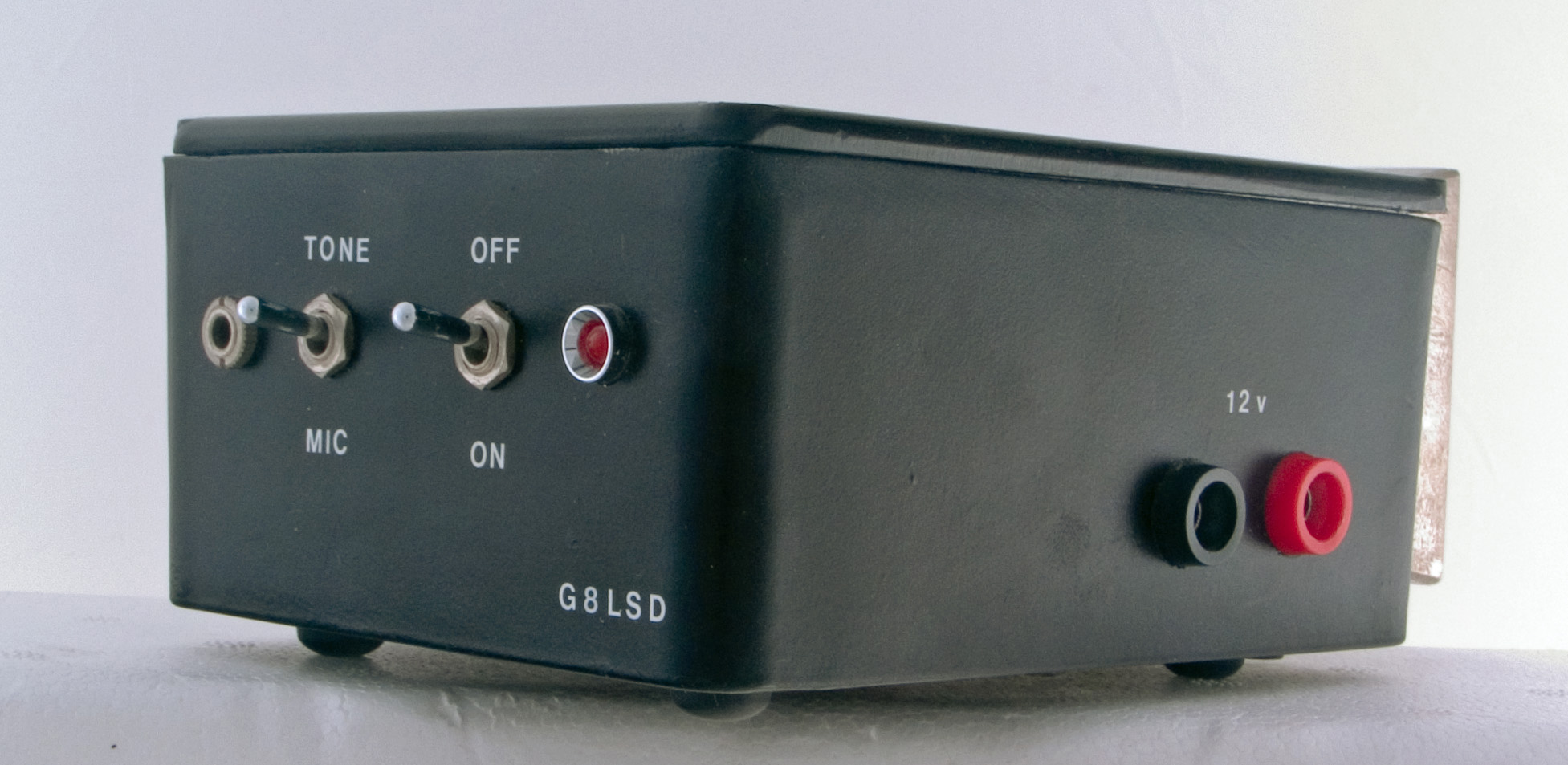
The beacon is mounted in a small die-cast box. The rear panel controls allow for power on and off and a choice of the pip-tone generator or a microphone to modulate the Gunn device. The microphone facility was added so as to be able to use this low powered beacon for demonstration purposes.
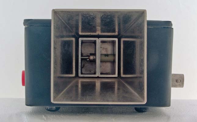
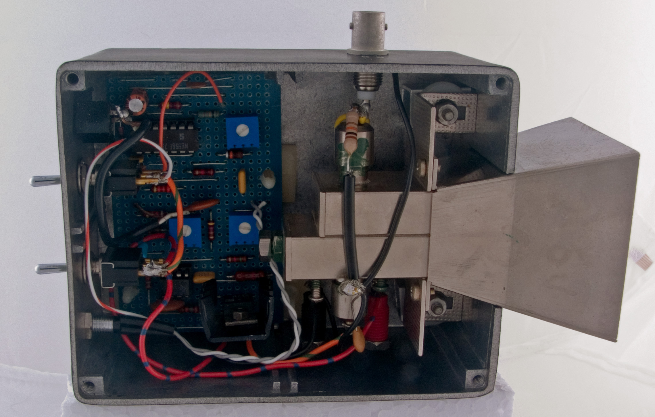
The main module in this simple beacon is a Wessex burglar alarm module. This features two cavities mounted side by side. Seen from the front the twin cavities are readily apparent. The right cavity contains the mixer diode and there is sufficient spill between cavities for the mixer to operate. The sensitivity is poor and these modules were guessed at having a noise figure of some 15 dB. Very deaf.
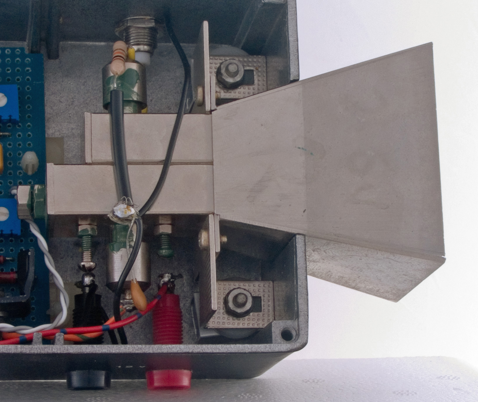
This arrangement of side by side cavities is unsatisfactory for normal microwave operation as the feed points of the cavities do not coincide and this gives rise to a significant squint. In this project the mixer diode is brought out to a BNC connector but in practice is not used. The transmitter cavity with its Gunn effect device is the active device used for the beacon.

The beacon operates from a 12 Volt battery and the Gunn supply is regulated so that the operating point and thus the frequency of operation is stable. To act as a marker the beacon requires some form of modulation and in this device a pip tone generator is used. The pip tone generator consists of two oscillators, one to provide approximately a 1 KHz tone and the other to turn the tone on and off several times a second. Only a few mV of the modulating voltage are required to be applied to the Gunn device to produce a wideband FM signal. The deviation is set to match the 75 KHz used in broadcast systems as the tunable IF in the PW EXE is a Band II tuner head.
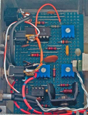
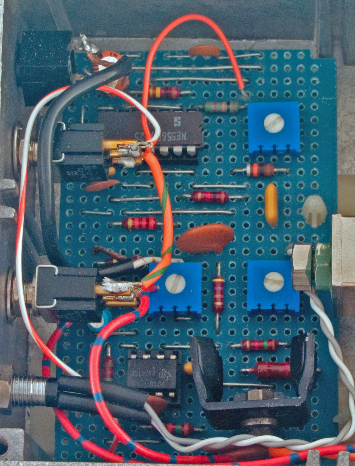
The voltage regulator transistor is seen mounted on a small heatsink at the lower right of the circuit board. The modulator circuit is taken from a design from the Microwave column of Rad Com and uses a 741 op amp and a pass transistor. The regulator element is a Zener diode. The pip tone generator is built around a 556 chip. This chip is a dual 555 timer in a 14 pin DIL module.

The longer cavity houses the Gunn device and to the left of the feed-in choke can be seen a 4 BA screw, this is the tuning mechanism and it is has a very course action. To adjust the frequency the locking nut is loosened and the screw very gently moved until a pink is heard in a receiver. The lock nut is tightened to secure but by tightening the nut the frequency is altered. So a process of progressive tightening and screw adjustment is required to achieve an accurate result.
The die-cast box measures 120 x 95 x 55 mm. The horn flares to 55 mm square. The overall length is 165 mm.
|