|
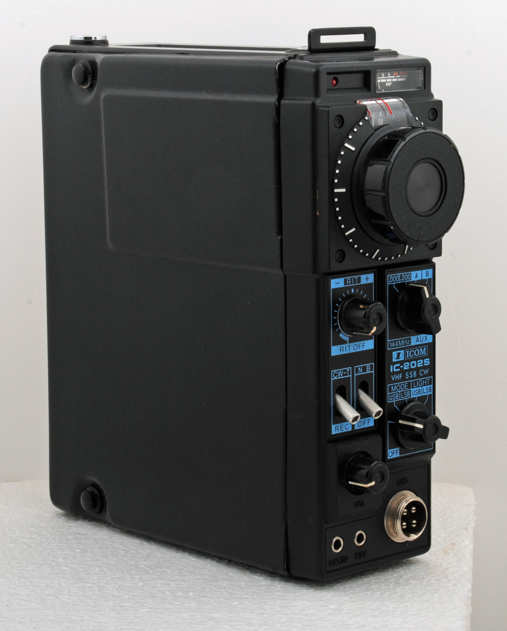
The IC202 is a 3 Watt 144 MHz transceiver. The variable frequency crystal oscillator provided a VFO style of operation in 200 kHz bands with a stability of 200 Hz/Hour that was not found in late 1970s VHF equipment. A PDF copy of the manual can be found here.
For many years the IC202 has been the IF of choice for amateur microwave equipment. The microwave front end transverter or receive converter would be of fixed frequency and down convert to a convenient IF frequency. This would normally be either 144 MHz or 432 MHz 144 MHz had the advantage of lower NF front ends for less money than 432 MHz. With the variable crystal oscillator in the IC202 the stability of the tunable IF was preferable to the wide range of a VFO driven IF system. Most operation of CW and SSB equipment would be in narrow segments of the amateur allocation and the restricted tuning range was not an issue.
Wide-band systems based on klystron transmitters would use FM modulation and the receiver IF bandwidth would typically be about 1 MHz wide as the transmitter stability was poor. Gunn effect transmitters enabled the IF bandwidth to be reduced to the point where broadcast FM receivers with 75 kHZ bandwidth were effective. Later developments enabled the IF to be reduced to 50 kHz but as these systems were being developed the advent of affordable narrow-band systems overtook this work. The narrow-band systems worked with the normal amateur standard band-widths of 5 kHz for FM and 2.7 kHz for SSB. Holding a 10 GHz stable for SSB was not easy in the 1980s and 1990s and very difficult in the years before.
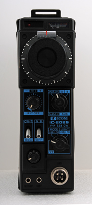
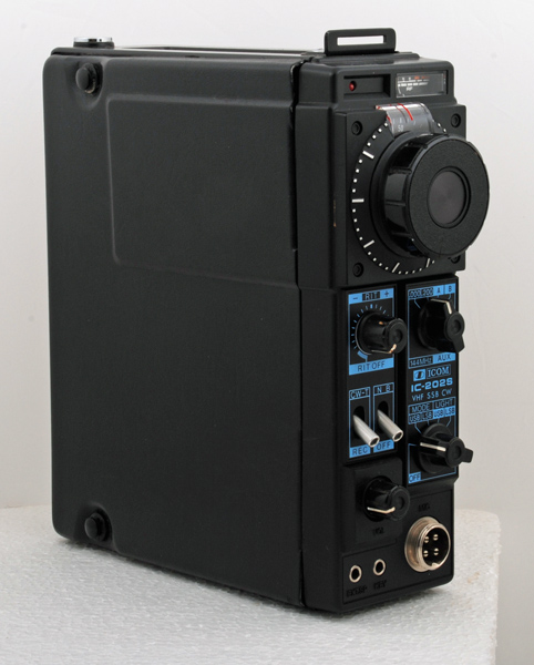
The design follows the military manpack approach and is functional without little used extra features. The external speaker and key sockets are at the bottom and the top is dominated by the large tuning knob.
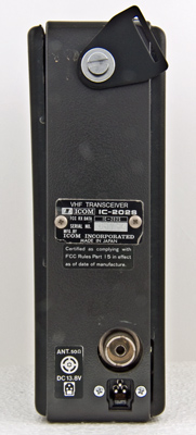
The rear panel has an input socket for a 13.8 Volt supply and a UHF connector for an external aerial.

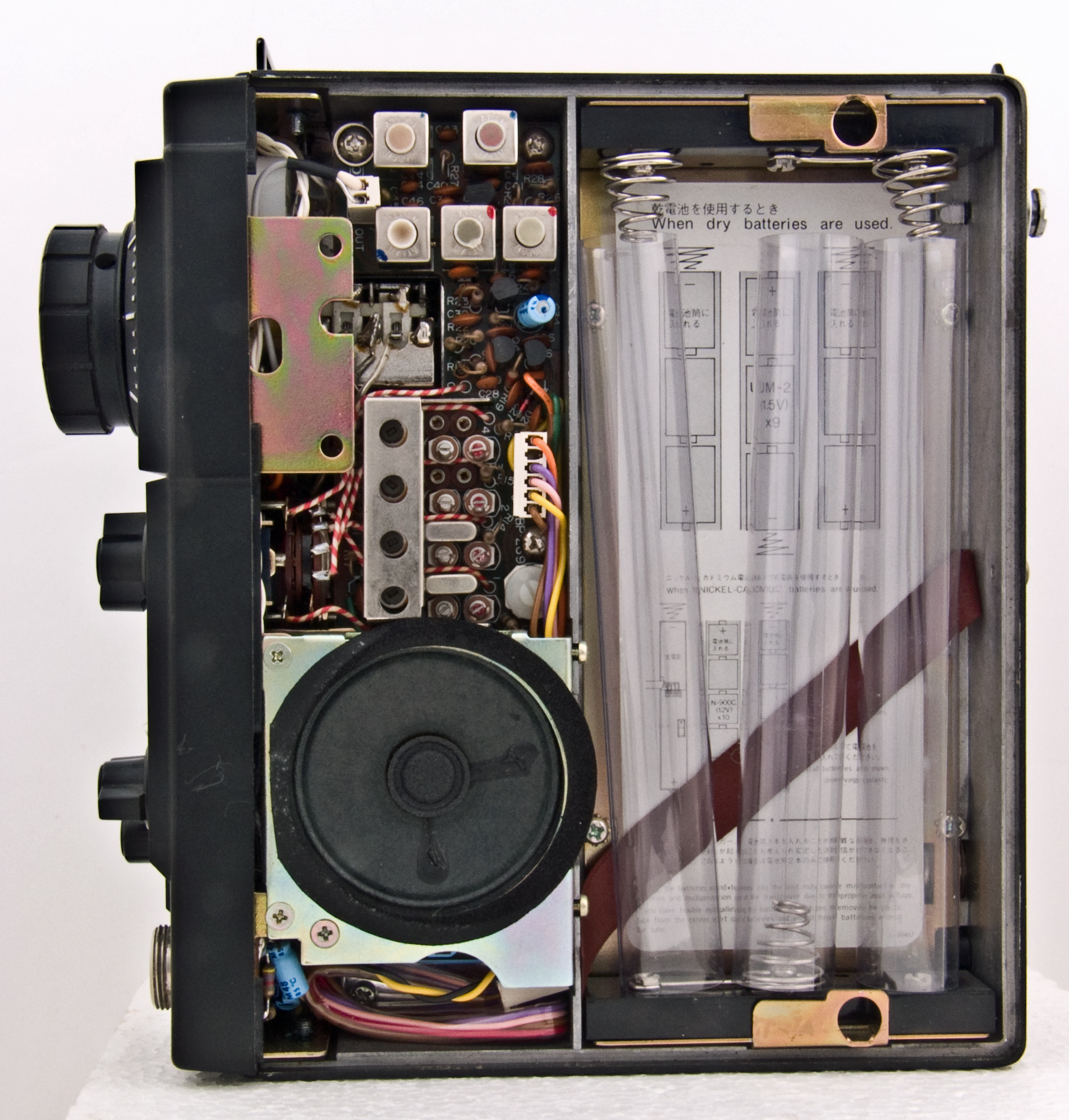
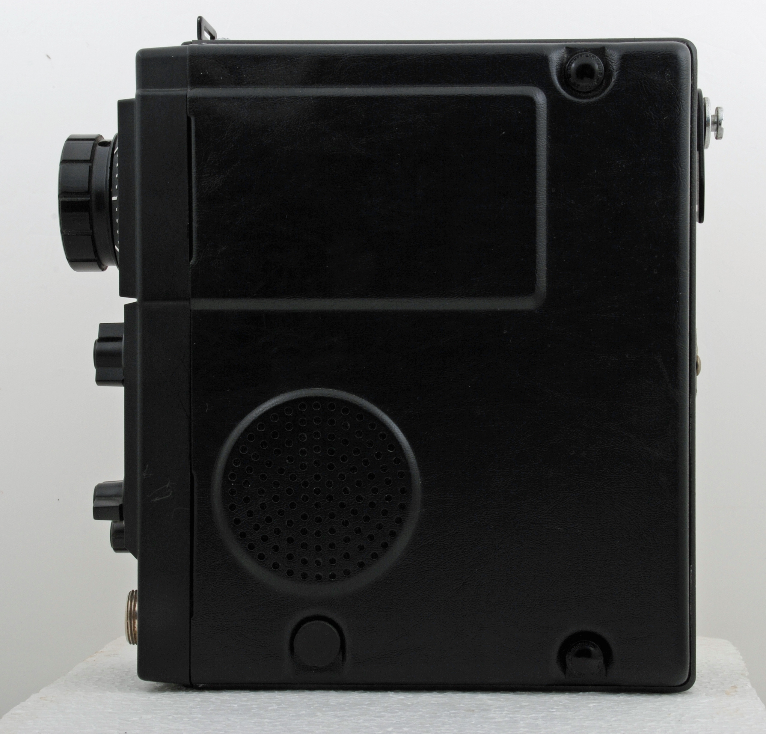
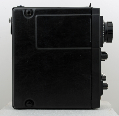
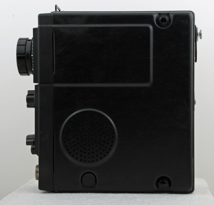
The side panels have push fix fastenings. On the speaker side is the battery compartment for 9 C sized Ni-Cad batteries. The IC202 consumed only 750 mA when key down TX in CW mode.

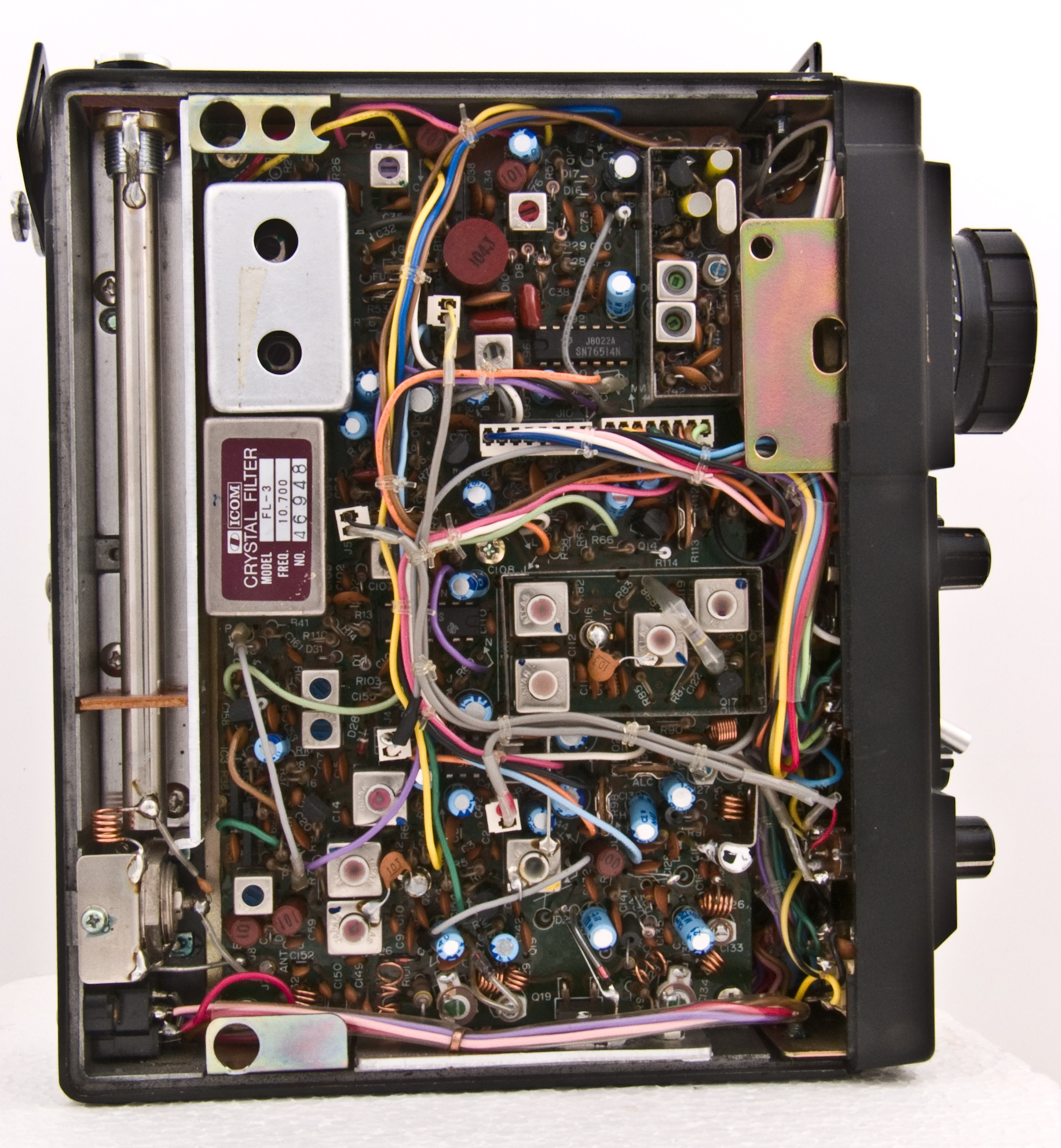
The main circuit board and housing for the built-in telescopic aerial.
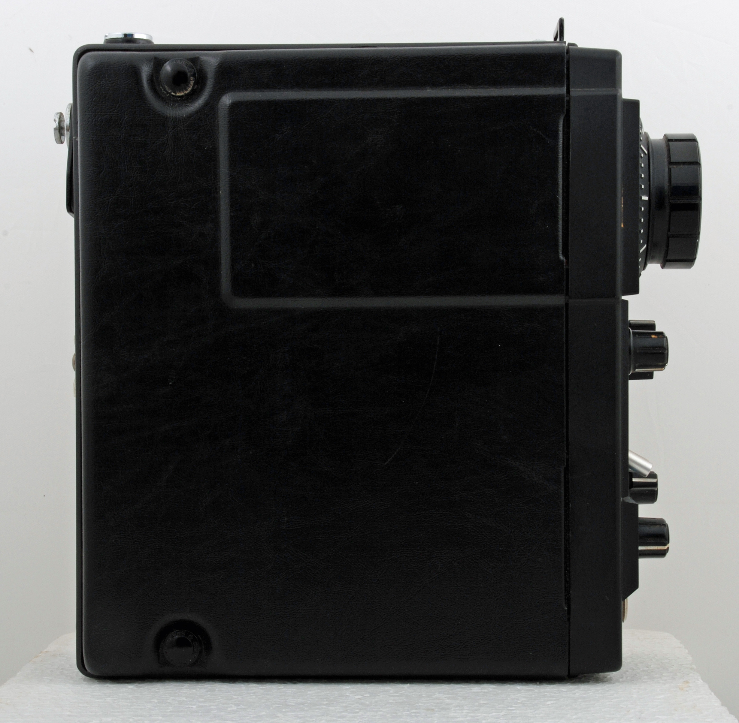
With side panels attached. The top of the die-cast case held fixings for a strap so that the unit could be used portable.
The base was flat so that the IC202 could stand on a surface for fixed operation.
The cabinet 190 mm tall, 190 mm deep and 60 mm wide. The tuning knob is 39 mm in diameter.
|