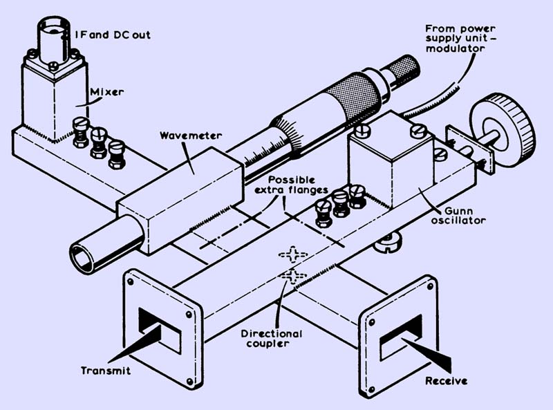
For the efficient operation of mixer diodes, they must receive the correct level of local oscillator injection. For diodes of the 1N23 series, this level is approximately 0.25 to 0.5 mW; for the SIM2, SIM5, CV2154 and CV2155 series, 0.5 to 1 mW, and for Schottky diodes about 2 mW. These levels correspond to mixer currents of approximately 0.25 to O.5 mA, 0.5 to 1 mA, and 1.5 mA respectively. The coupling coefficient of the directional coupler required to produce these levels is simply the ratio of the power of the RF source to that appropriate to the mixer diode in use. For a 50 mW klystron and an SIM2 diode, this ratio is 50:1, ie 17dB. For a low-power Gunn oscillator of output 5 mW to a 1N23 diode, this ratio is equivalent to 10 dB. If a lower coupling is possible, then designs of directional coupler, which are somewhat simpler to make, may be used. In a typical system employing a 10 mW source, a 10 dB coupler could be used: of this power, 1 mW would be dissipated in the mixer diode, and 9 mW would appear at the transmit port (a few micro-Watts only should appear at the receive port). Note that the input signal power is attenuated in the same proportion, and 10 per cent of the signal is coupled from the receive port to the transmit port and is lost, although the loss is insignificant. When the unit is used as a receiver, the transmit port should preferably be terminated in a matched load as this improves the frequency stability of the RF source. If the RF power even approaches 20 mW, then the transmit port should at all times be terminated in a load or an aerial as the radiation level at the open end of the waveguide can exceed the maximum safe level of 10 mW/cm2. Some general points on various components will be useful: Gunn oscillators. The design of a Gunn oscillator is given in Gunn Diodes at 10,000 MHz, and other designs, claimed to be more reliable in operation, are being prepared. Note that it is worthwhile being able to tone modulate the local oscillator of a receiver as this enables CW signals to be detected. Check any PSU carefully for HF and VHF parasitic oscillations. Klystrons. Type 723A/B and Type K308 are suitable. Duplex. For duplex working a 30 MHz IF is standard. |


