|
Since G8DEK directed the attention of visitors at the last Winchester round table to the possibility of stabilizing Gunn oscillators by locking them on to ordinary wavemeters a number of people have followed this up with enthusiasm and not a little success. In his system, G3KSU simply fitted a wavemeter close to the oscillator with the output being fed to the external circuitry via an isolator. The wavemeter, the Q of which is believed to be in the region of 200, produced a dip about 2 dB deep and 30 MHz wide. When the Gunn oscillator was tuned about half-way down the LF side of the dip, three things happened: the oscillator locked on to the wavemeter; the oscillator would remain locked even when the wavemeter was tuned over plus or minus 15 MHz, and the noise bandwidth of the Gunn oscillator was sufficiently reduced so that narrow-band signals, which were previously unintelligible in a 3 kHz IF bandwidth (!), became perfectly readable When the wavemeter was brought into action.
The stability of the oscillator will obviously depend on the Q of the wavemeter employed. G3KSU is currently investigating specimens having Qs of 2,000 and 5,000. The frequency range of stabilization also depends on the amount of power that one is prepared to lose. G8DIC, who has also been experimenting with this technique, found that his system stabilized over a 5 MHz range with only a 0.5 dB loss.
The locking process depends on the power reflected by the wavemeter at resonance being in the appropriate phase. G8DEK's original suggestion was to use a phase shifter to ensure this. G3JVL reports that if the position of the wavemeter is such that it is difficult to lock the oscillator, then fitting a 'tuning' screw anywhere between the wavemeter and the oscillator usually provides enough phase shift to allow locking.
This topic was again discussed at the round table held on 13 November when further details were given of the successful results that had been obtained. This meeting will be reported in the near future but in the meantime preliminary details of one approach are given so that people can start to experiment.
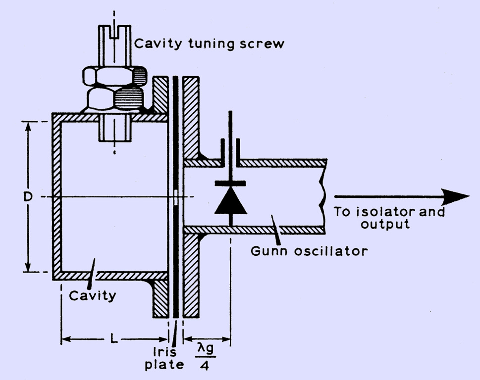
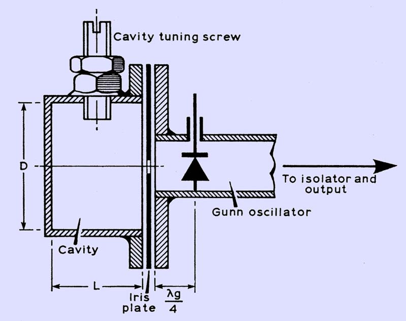
In the technique shown in the diagram above, the cavity is fitted to the rear of the oscillator. The length of guide between the Gunn diode and the cavity is made λg/4 (or presumably any odd number of quarter guide wavelengths). A suitable cavity uses the TE111 mode for which the dimensions are given by the relationship:
(f*2 D*2) / 10,000 = 3.2 + 2.22(d*2/L*2) . . . (1)
where f is in gigahertz, D and L in millimetres.
To minimize the risk of the cavity operating on the wrong, mode, it is recommended that the value of (f*2 D*2)/10,000 should be between 7.5 and 11 (2). The corresponding values for L, which must be calculated precisely from (1), will then lie between 0.5 D and 0.7 D.
Care must be taken in the construction of the cavity in order to maintain its Q. Professionally they are usually made from a low-expansion alloy such as Invar which subsequently is plated with gold, for example, to reduce its skin resistance to an acceptably low value. A practical alternative for amateurs is copper, the only disadvantage of which is that the resonant frequency of the cavity will vary with its temperature. To produce a high-Q cavity (and the unloaded Q may easily be 10,000), as much as possible of the material used should be copper, ie the cavity itself, the tuning screw and the iris plate. The inside surfaces of the cavity should be polished, and the amount of solder used inside the cavity should be kept to a minimum.
As an example of the design of a cavity, consider one of maximum frequency 10.6 GHz, which will tune into the amateur allocation. Substituting this frequency in (2) produces preferred values for D of 26 to 33 mm. A convenient source of copper tube within this size range is the standard water pipe, which has an inside diameter of 26.5 mm. Substituting this value for D in equation (1) produces the value for L equal to 18.1 mm. A 2 BA or similar screw inserted parallel to the E-plane will tune the cavity over a few hundred megahertz.
It is suggested that the size of the iris coupling the oscillator to the cavity be such that the output of the oscillator is reduced by a maximum of about a third (ie about 2 dB) as they are tuned together.
|