|
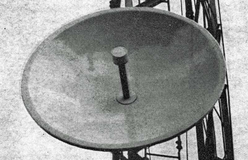
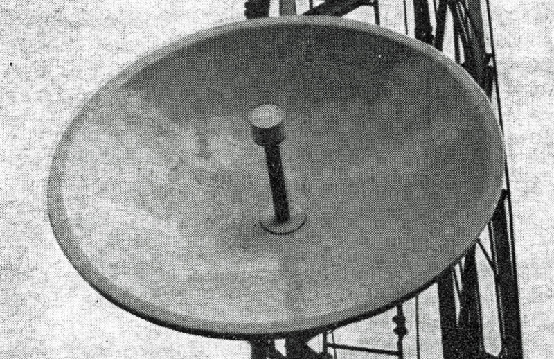
The Author's 4 ft solid dish.
It is surprising, considering its importance, what little information there is concerning the design and construction of the paraboloid aerial. At frequencies above 1 GHz it is doubtless the optimum aerial for the type of usage put to it by radio amateurs.
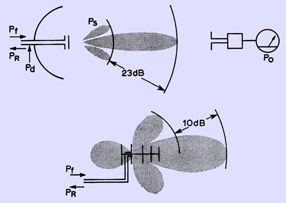
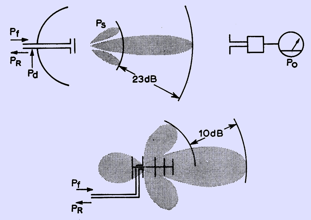
Comparing sources of power loss in a dish and a Yagi. For the Yagi, Pr Pd and Ps will be large and so Po will be lower than hoped for.
The main reason for this is the easily obtained high efficiency; ie the ratio of power in the far-field main lobe to that in the feeder, see above. In this context it must be compared to a Yagi, a stacked dipole array or a corner reflector-with these aerials, excellent though the first two are at lower frequencies, power is lost in various ways due to the mechanics of the structure. Efficiency is thus lower for a great many designs which attempt to scale these aerials down for use at higher frequencies. Table 1 compares the gains of typical aerials for 7O cm and above. To some extent the question of aerial gain is subjective in the amateur sense, since few have access to equipment which will discriminate to within 2 dB or so at 1,300 MHz, but it has been concluded on this basis that the parabola emerges far ahead of its rivals for 1,296 MHz and above.
Aerial Gain Comparison
Aerial | 70 cm | 23 cm | 13 cm | 9 cm | 3 cm |
Yagi, 14-el | 16 dB | 13 dB | - - | - - | - - |
Horn/trough | 10 dB | 18 dB | 25 dB |
32-el stack | 15 dB | 13 dB | - - | - - | - - |
4 ft dish | - - | 22 dB | 27 dB | 30 dB | 40 db |
The gain of a dish, as a working guide, is:-
G = 10 log10 ((kπ*2D*2)/(λ*2)) dB ...(1)
where k lies between 0.6 and 0.7, D is the diameter and λ is the wavelength. This formula was used to obtain the gain figures shown in Table 1. One point about this expression which is made in (1) is that this gives again 2 dB down on an ideal stacked co-linear of the same area. The emphasis here of course, is on the word ideal.
Inevitably when designing a dish, resort must be made to a formula or two:-
y*2 = 4.f.x = 4.(f/D).D.x ...(2)
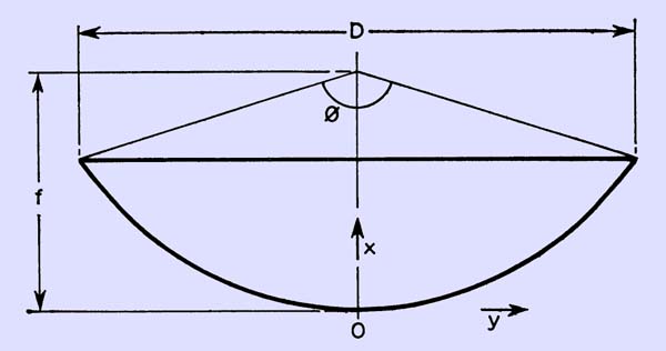
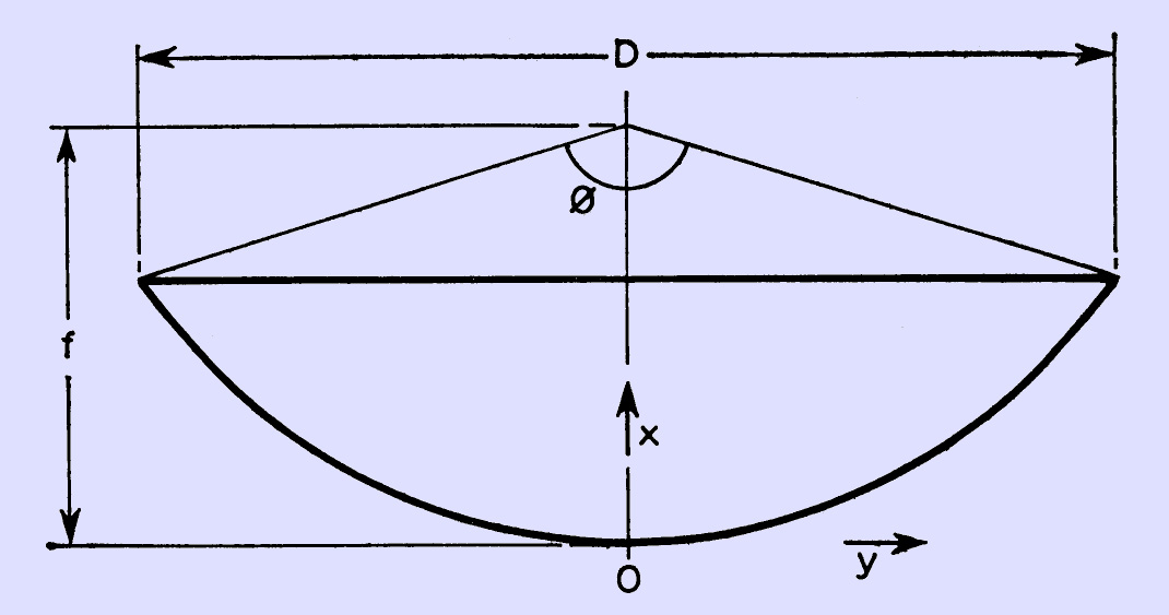
Diagram showing the directions of X and Y as well as the subtended angle.
are two very important ones. They relate distance along a radius to distance along the focal axis, as shown in the diagram above. It is clear from these that the focal length, f, is a critical factor in the design, although it is not clear what influences its choice. The chief influence is the feed to be used. This point is shown below.
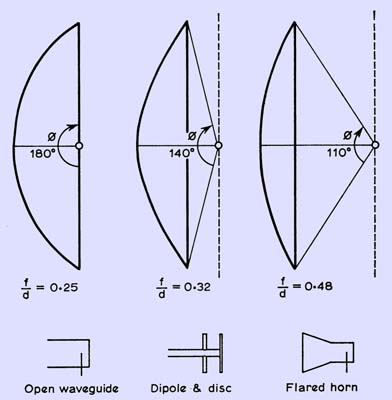
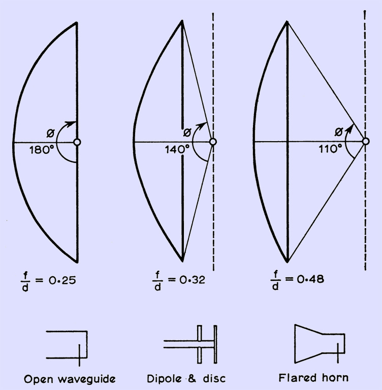
Three dish profiles with appropriate feed for each.
The curvature of the profile is usually specified by a parameter f/D, which is the ratio of focal. length to diameter. For this reason it has been incorporated into equation 2. In effect this specifies the angle subtended by the rim at the focus, where the feed is situated. The two are related through the formula
f/D = t¼cotan(φ/4) ...(3)
It is immaterial what gain (and, thus, beamwidth) the feed has, provided that the appropriate choice of f/D is made to suit it. If this is done, the best compromise level of radiation will be intercepted and reflected by the dish. The level which is intercepted by the rim is expressed relative to the main lobe maximum of the feed, and is called 'edge illumination'. The level chosen is generally about -10 dB below peak level, below which power is allowed to 'spill over'. If too much is allowed to spill (f/D too large, dish too shallow) then the front to back ratio suffers. Power is lost from the main lobe, and efficiency falls. If too much is intercepted, (f/D too small, dish too deep) then, due to excess curvature, cross-polarization and defocusing occur. The forward gain, and, thus, efficiency, decreases again. The f/D ratios for typical feeds are shown above.
The optimum subtended angle is shown in [1] to be 1000 to 1200, and from equation 3 this means a ratio of f/D = 0.48. An eminently suitable feed would be that given in [2] providing three-band coverage (23 to 9 cm) and near optimum directivity for the optimum of f/D ratio. With an edge illumination level of -10 dB, the expected side-lobe level for a well-constructed dish is about 23 dB assuming a perfect paraboloid contour.
Amateur construction will generally fall rather short of the ideal. This not only causes side-lobes to bristle, which can be good, but also causes gain to fall, which is bad. The tolerance thought to be adequate for amateur purposes is 1/8λ at the highest frequency of operation.
Construction techniques are many and varied. For small dishes about 3 ft in diameter, or those for occasional use, a solid reflector is practicable. For permanent use, portable use in typical VHF NFD weather, or for moon-bounce, a mesh reflector is desirable. It reduces weight, windage and cost. A design not often seen is a skeleton reflector although for 23 cm this is a simple, light-weight design.
Two types of construction which the author has successfully used will now be described in some detail.
Solid Reflector
By far the most versatile material used has been glass fibre reinforced with polyester resin. It does require, however, a certain amount of panache and a fairly deep pocket. Trials with small quantities are strongly recommended. A mould of some sort is essential and one short cut is to use someone else's solid dish as the mould. Failing this, sand for the purpose is cheap, easy to handle and readily available.
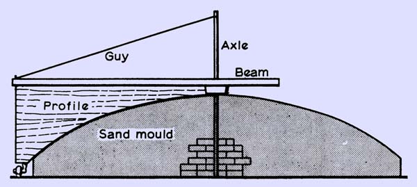
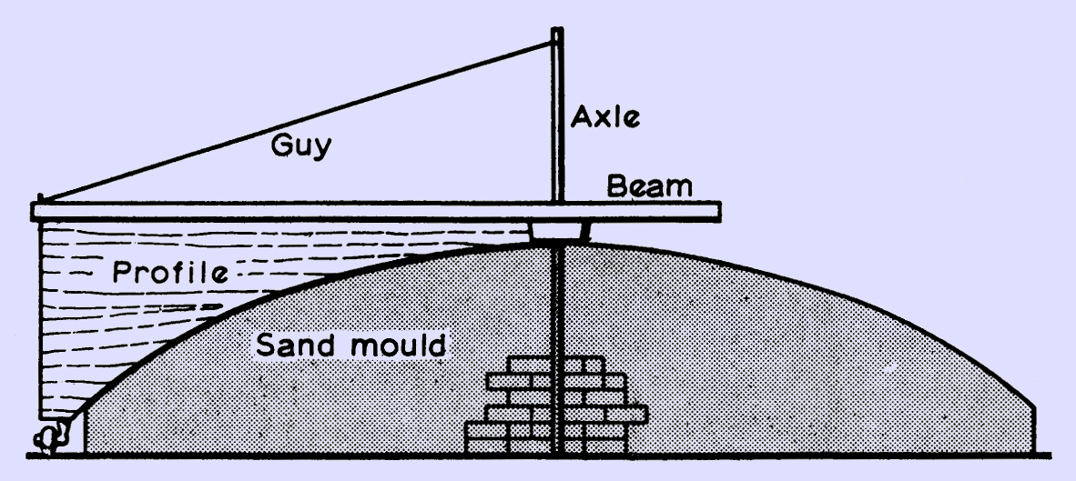
The preparation of the sand mould for a solid dish.
Support a central axle in the sand, using whatever method ingenuity suggests. Pivot a beam supporting a profile cut using either formula (2) or the device shown in below. Rotate this profile around the axis, either adding or cutting away sand as necessary. This should leave a beautiful paraboloid shape. Remove the beam and profile. Allow the top surface to dry thoroughly, and apply sufficient paint from a spray-on tin to fix the surface firmly enough to work on. Now lay up the glass fibre and resin, preferably pre-impregnating the glass fibre before laying up. Continue this until the required thickness is achieved, which, as a guide, is about ¼ in for a 4 ft design. Cut eight ribs to the same parabolic profile in tin or fin plywood and use these to reinforce the structure by bonding onto the back of the dish with resin and glass fibre.
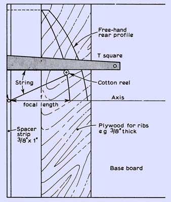
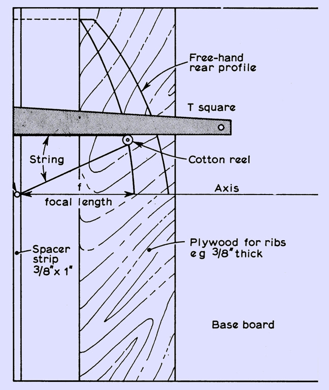
Draughting device for drawing dish profiles.
Allow a week for hardening, and do not allow any moisture to settle on the surface. A heater nearby is a good idea during this time, provided it is kept away from resin and cellulose thinners. When the resin is hard remove the shell from the sand by twisting and lifting. Leave the inside face exposed for a day or two to ensure complete setting, and then, with the aid of a wire brush and cellulose thinners (NO SMOKING, PLEASE!), remove as much of the sand adhering as enthusiasm dictates. Clean off all thinners and leave for another day. Next apply resin to the surface and brush on pre-cut sections of aluminium kitchen foil. Allow this to set, and paint to taste.
Profile values in inches for a 4 foot dish, f/D = 0.31
X | Y |
0.16 | 1 |
0.63 | 2 |
0.14 | 3 |
0.25 | 4 |
0.39 | 5 |
0.57 | 6 |
0.77 | 7 |
1.01 | 8 |
1.28 | 9 |
1.58 | 10 |
1.91 | 11 |
2.27 | 12 |
2.67 | 13 |
3.09 | 14 |
3.55 | 15 |
4.04 | 16 |
4.56 | 17 |
5.11 | 18 |
5.70 | 19 |
6.31 | 20 |
6.96 | 21 |
7.64 | 22 |
8.35 | 23 |
9.09 | 24 |
Mesh Reflector
The mesh normally used is chicken wire. The hole size should be less than O.lλ diagonally at the highest frequency of operation. The mesh must be supported by ribs, either of wood or of steel-angle for larger structures. If wood is employed, the ribs can be cut using formula (2), or use can be made of the draughting device shown below. Usually eight ribs will be necessary, although this depends to some extent on dish diameter. A suitable rib material for diameters up to 8 ft is Contiboard, but for diameters less than 4 ft 3/8 in ply is adequate.
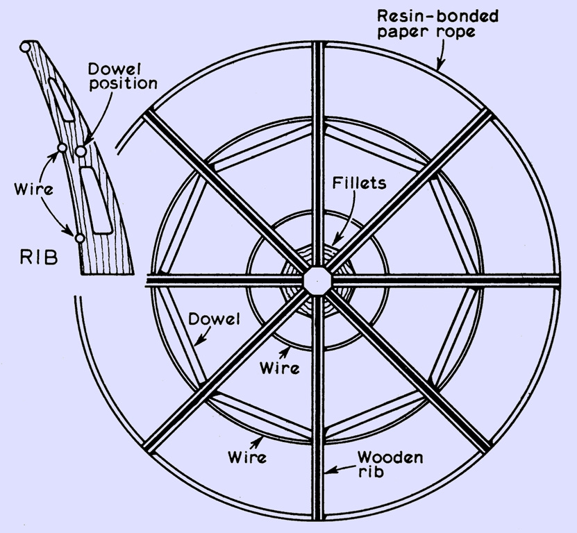
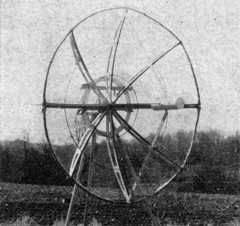
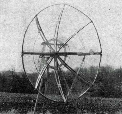
Using the draughting device (above) draw a line AB, shown also as 'axis'. Cut a length of twine slightly over twice the focal length of the dish and pin one end to the baseboard spacer block at A. Loop the twine round a cotton reel and pin the other end to the T-square at C. Run the square out from the axis to position D, where AD is equal to the dish radius. Position the rib-board so that the edge coincides with the hole in the cotton reel. Put a pencil through the hole and run the T-square back towards the axis, keeping the twine taut and the reel against the T. Mark in the back line of the rib with a free-hand line which indicates enough strength for the material in use. Cut-outs can be incorporated to reduce weight, but beware of decreasing the strength. Cut the rib out using an electric drill jig-saw attachment, using the first profile to draw the subsequent ones. The diagram below shows how the ribs are assembled in a spider, and below is a photograph of the author's 6 ft dish which was made in two halves for easy transportation. The circles were made from Pyrotenax cable, the rim being reinforced with resin-bonded paper rope. Ordinary rope should suffice, but the resin must be worked well in. Sections of chicken wire were cut when the spider had been assembled and were clipped onto the circles at appropriate intervals using 22 SWG tinned copper wire. A coat of paint completed the job.
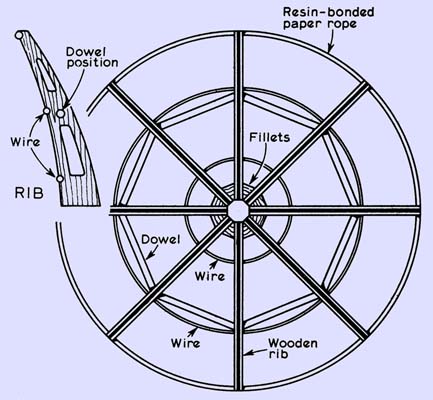
Framework for an open mesh reflector.
Summary
Briefly, the steps in design are:
1 | Decide what gain or beamwidth suits the application; |
2 | Decide what type of feed is suitable for the job; |
3 | From its design estimate the width, to -10 dB, of the main lobe; |
4 | Use formula (3) to calculate the f/D ratio; |
5 | Use formula (2) to compute the profile, or use the draughting aid; |
6 | Decide on solid or mesh, and consult appropriate section. |
Conclusion
The increased use of the amateur microwave frequencies has led to a demand for practical aerial designs for amateur use, but the designs described have one serious drawback, the signal is not only concentrated in the vertical plane but also in the azimuth plane. Some thought by those who are concerned to see these bands more effectively used will show what a serious limitation this is to their widespread use. A far more useful design would give a wide fan beam in the horizontal plane, while still restricting radiation as much as possible in the vertical. An aerial of this type is currently being developed, and it is hoped that a report will appear in due course.
References
- Microwave Antenna Theory & Design, S. Silver (esp. Chap. 12)
- Wide-band Aerial Structures, C R Fry, G3NDI, RSGB Bulletin, November 1966
|