|
G3JVL has supplied details of the mixer which is in use by both stations as a receive and transmit converter for the regular tests between Oxford and Hayling Island.
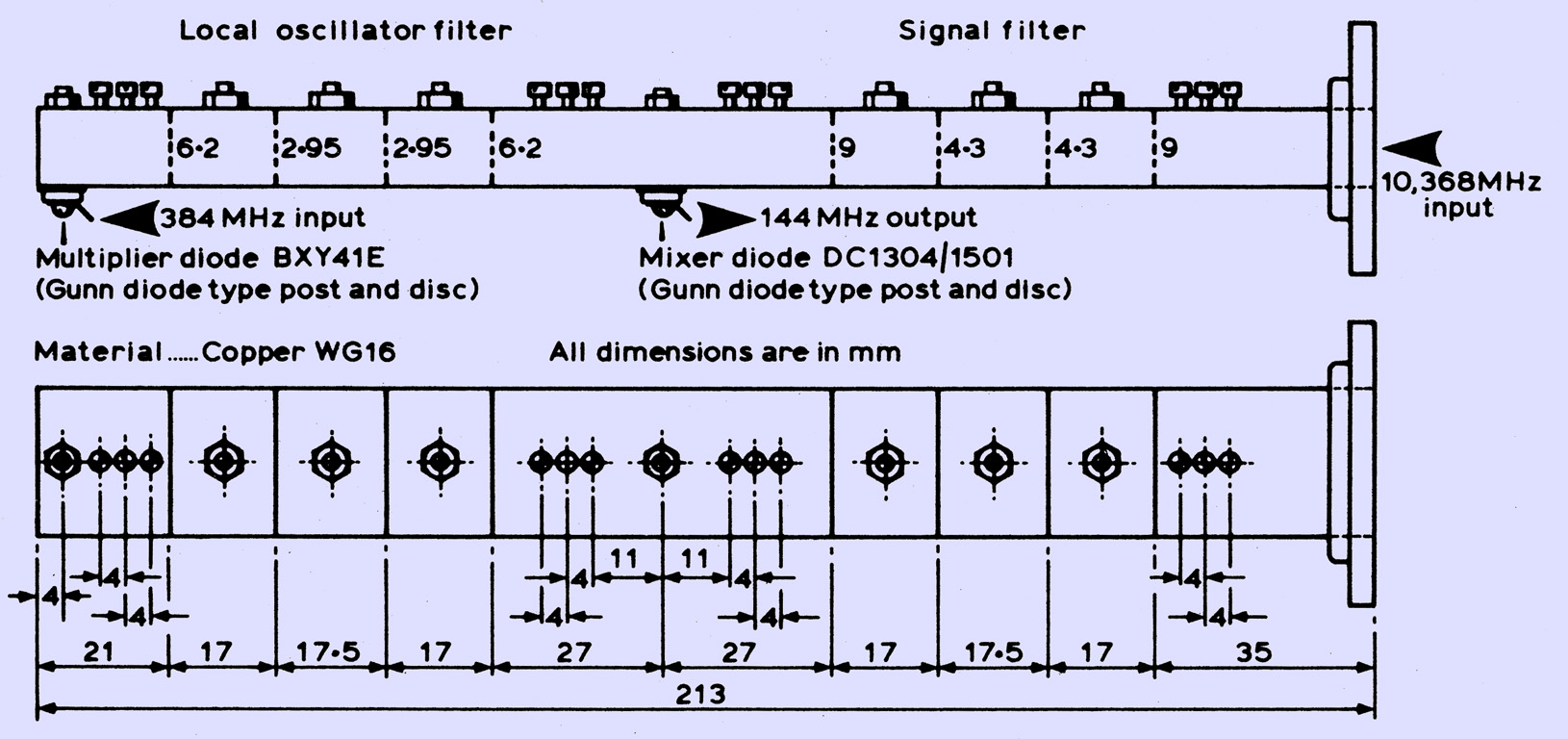
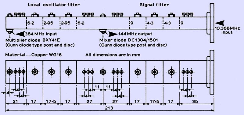
The unit consists of a mixer diode mounted between two filters, one on the local oscillator frequency (10,224 MHz), the other on the signal frequency (10,368 MHz). The local oscillator filter is designed for maximum rejection of local oscillator noise, and is therefore a very narrow band device, while the signal filter is designed primarily for low loss, and is therefore somewhat broader. See Designs for 10 GHz bandpass filters for the construction of these filters. The relevant dimensions, ie the spacing and diameter of the iris holes are given here in the illustration above.
Both the multiplier and mixer diodes are mounted using Gunn diode type posts and discs. The matching into the multiplier diode can be the same as that described in Microwaves (March 1976). The diode requires, typically, 0.5-1W drive at 384 MHz. G3JVL also has an alternative matching network.
The mixer diode is a GaAs Schottky barrier type, of AEI manufacture. Devices of the same type by other manufacturers are probably also satisfactory. The 144 MHz IF output is fed by a suitable matching network to a low-noise preamplifier. The matching will depend on the exact diode current used, and is best set up using an automatic noise figure meter.
The tuning up procedure of the mixer unit needs to be done carefully if optimum results are to be achieved. Initially monitor the mixer diode current with 384 MHz drive applied to the multiplier diode, and maximize this by using the local oscillator filter tuning screws and the tuning screws between the multiplier diode and the filter. Next, remove the 384 MHz drive and apply RF at 10,368 MHz to the input of the receiver. Tune the signal filter and all the rest of the matching screws for maximum current, reducing the RF input as necessary to keep the mixer current at the required 1.5 mA. Finally; re-apply local oscillator drive and optimize all tuning and matching adjustments for best signal-to-noise ratio using either a weak-signal source or, preferably, an automatic noise figure meter.
When optimized, the noise figure should be around 7 dB, allowing for a 1.5 dB noise figure IF preamplifier. This is a very good performance indeed, and will only be bettered by the use of an RF preamplifier.
G3YGF has demonstrated the efficiency of this design as a transmit converter, by feeding a few milli-Watts of 144 MHz SSB into the mixer diode. About 1 mW PEP output at 10,368 MHz can be achieved, which is adequate for local contacts or for driving a TWT amplifier.
|